SET-UP AND INSTALLATION MLC650 VPC-MAX™ OPERATOR MANUAL
4-10
Published 04-06-18, Control # 231-14
SWING LIMITS
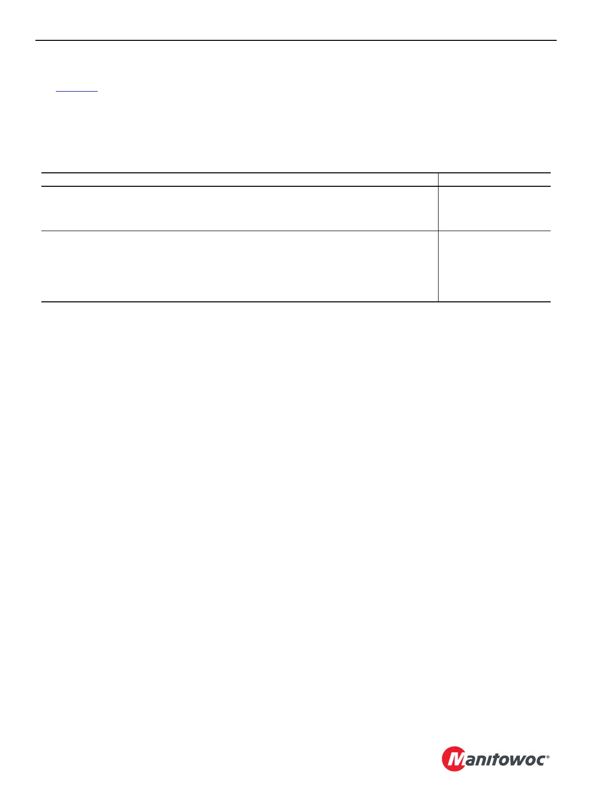
See Table 4-2 for swing limits during VPC-MAX assembly
and disassembly.
Refer to the MLC650 VPC-MAX Liftcrane Mast Handling
Capacities chart at the end of this section for detailed lifting
capacities with the fixed mast.
Table 4-2 Swing Limitations
Crane Configuration Swing
• VPC-MAX actuator and beam installed
• Counterweight tray, auxiliary frame, and counterweight boxes (Series 1, 2, or 3) installed
• Counterweight fully retracted
360° Swing Permitted
• VPC-MAX actuator and beam installed
• Counterweight tray, auxiliary frame, and counterweight boxes (Series 1, 2, or 3) installed
• Counterweight fully retracted
• Fixed mast installed and positioned at minimum radius given MLC650 VPC-MAX Liftcrane
Mast Handling Capacities chart
360° Swing Permitted