Manitowoc Published 04-06-18, Control # 231-14 4-9
MLC650 VPC-MAX™ OPERATOR MANUAL SET-UP AND INSTALLATION
2. Connect the two hydraulic hose connections to the two
connections on the hand-held pin puller (1, Figure 4-11
).
a. With the hand-held pin puller in position, pull on the
control knob (4) to extend (4a) the cylinder. Push on
the control knob to retract (4b) the cylinder.
b. The cylinder rod end (3) is used to push or pull pins
and the insert coupler (2) is used to align the pin
puller during insert pin installation or removal.
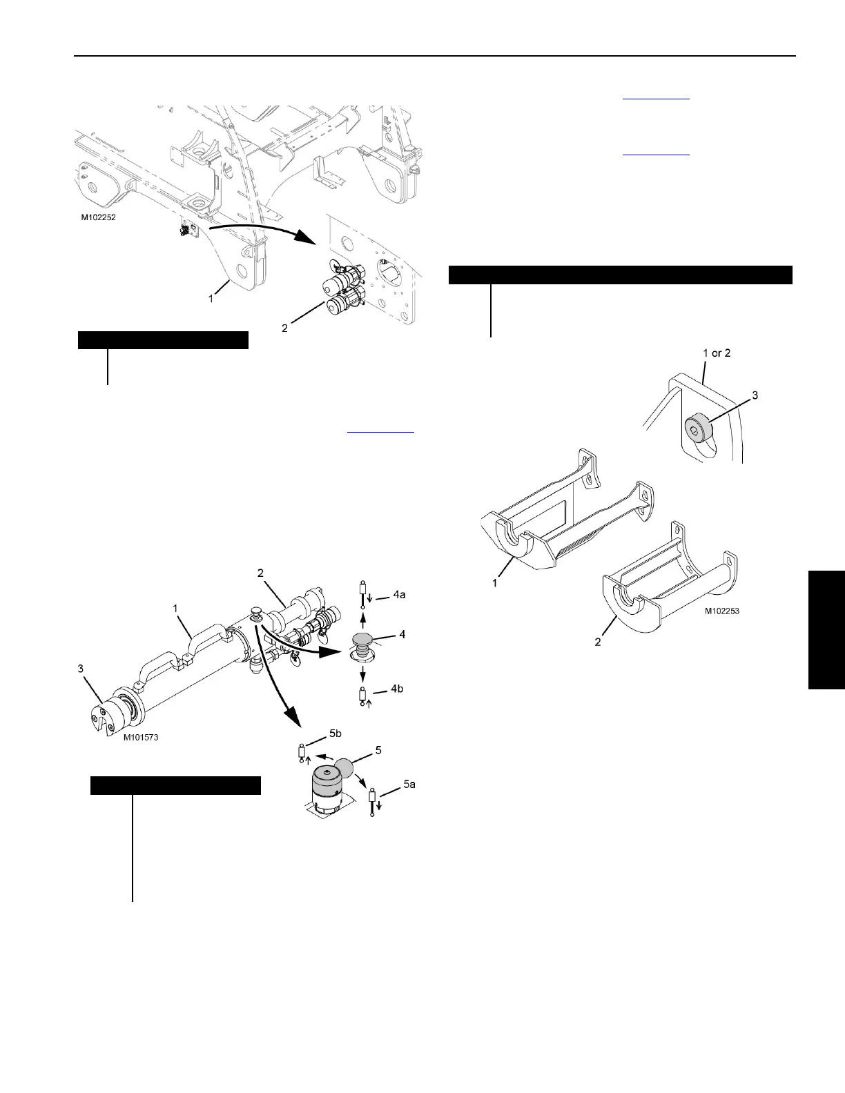
3. Install pin puller cage (1, Figure 4-12
) to install/remove
the following operating pins: boom hinge and the live
mast hoist (drum 4).
4. Install pin puller cage (2, Figure 4-12
) to install/remove
the following operating pins: gantry and the backhitch.
NOTE: Both cages are designed to slip over shoulder
screws (3) mounted on the crane for quick
installation and removal of the cages.
Item Description
1 Rotating Bed
2 Hydraulic Connections
FIGURE 4-10
Item Description
1 Hand-Held Pin Puller
2 Insert Coupler
3 Cylinder Rod End
4 Control Knob
4a Pull to Extend
4b Push to Retract
FIGURE 4-11
Item Description
1 Pin Puller Cage (for boom hinge and live mast hoist pins)
2 Pin Puller Cage (for gantry and backhitch pins)
3 Shoulder Screw
FIGURE 4-12