SET-UP AND INSTALLATION MLC650 VPC-MAX™ OPERATOR MANUAL
4-42
Published 04-06-18, Control # 231-14
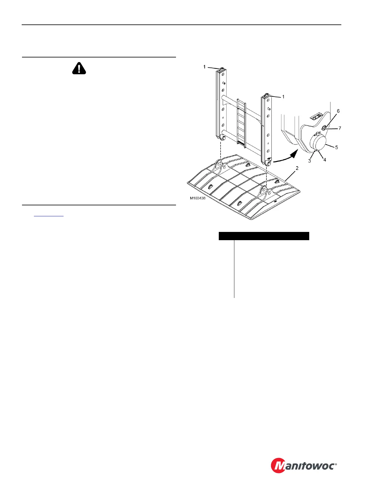
Installing the Auxiliary Frame Assembly
See Figure 4-39 for the following procedure.
1. Using an assist crane, attach two SL 4 slings – 3,80 m
(12.50 ft), 11 340 kg (25,000 lb) – to the auxiliary frame
lift points (1).
2. Hoist the auxiliary frame into position to install to the
pad (2).
3. Remove the cotter pins (3) from each of the retaining
pins (4).
4. Remove the retaining pins from the clevis pins (5).
5. Remove the clevis pins.
6. Remove the lynch pins (6) from each of the secondary
pins (7).
7. Remove the secondary pins.
8. Install the auxiliary frame to the pad.
WARNING
Structural Damage Hazard!
A sudden release of load and/or dynamic loading (due to
swinging, hoisting, or lowering and adverse weather
conditions to include wind) may cause structural damage
due to shock loading and unintended motion of the crane.
The auxiliary frame assembly is provided to limit
unintended motion of the VPC-MAX beam and
counterweights during a sudden release of load and/or
dynamic loading (due to swinging, hoisting, or lowering
and adverse weather conditions to include wind).
The auxiliary frame assembly in no way substitutes for, or
lessens, the requirement that the crane must be operated
properly and safely, and that it must be inspected,
serviced, and maintained regularly to minimize the
potential for a sudden release of load and/or dynamic
loading (due to swinging, hoisting, or lowering and
adverse weather conditions to include wind).
Item Description
1 Auxiliary Frame Lift Point (qty 2)
2Pad
3 Cotter Pin (qty 8)
4 Retaining Pin (qty 4)
5Clevis Pin (qty 2)
6 Lynch Pin (qty 4)
7 Secondary Pin (qty 2)
FIGURE 4-39