SET-UP AND INSTALLATION MLC650 VPC-MAX™ OPERATOR MANUAL
4-94
Published 04-06-18, Control # 231-14
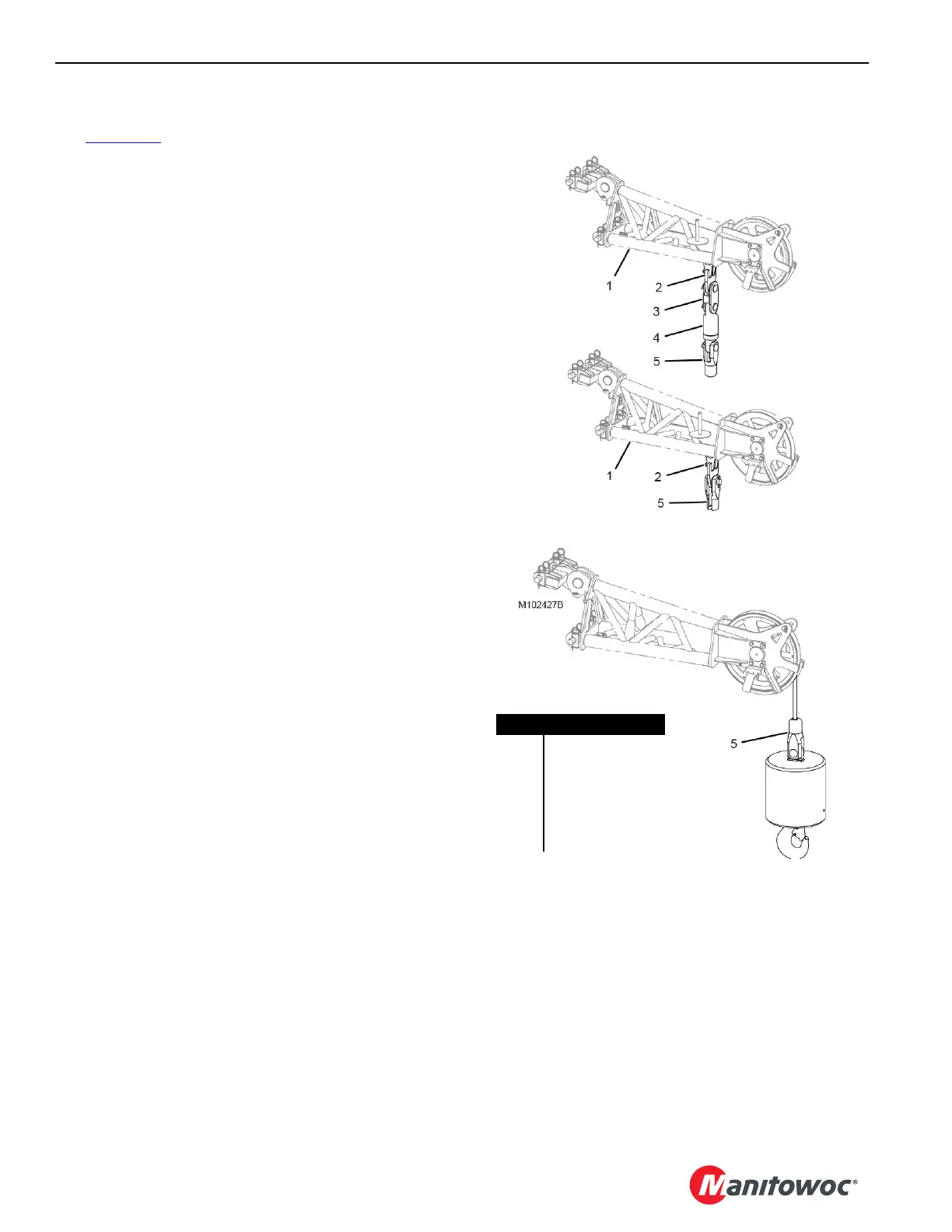
Dead End Locations
See Figure 4-79 for the upper boom point dead end locations
and required hardware.
See the Boom Rigging Drawing for the lower boom point
dead end locations and required hardware.
All hardware is stored in the job boxes provided with the
crane.
INSPECTING THE VPC AND VPC-MAX
ROLLER PATHS
Prior to using the crane each day, inspect the VPC and VPC-
MAX roller paths on the rotating bed and beam for obvious
obstructions and/or signs of damage. Remove the
obstructions. Contact the Manitowoc Crane Care Lattice
Team for inspection and repair criteria.
FIGURE 4-79
Upper Boom Point Multiple Parts of Line
Upper Boom Point Single Part of Line
Item Description
1 Upper Boom Point
2 Dead-End Link
3Link
4Swivel
5 Button Socket –
28 mm or 32 mm