MAINTENANCE MLC650 VPC-MAX™ OPERATOR MANUAL
6-14
Published 04-06-18, Control # 231-14
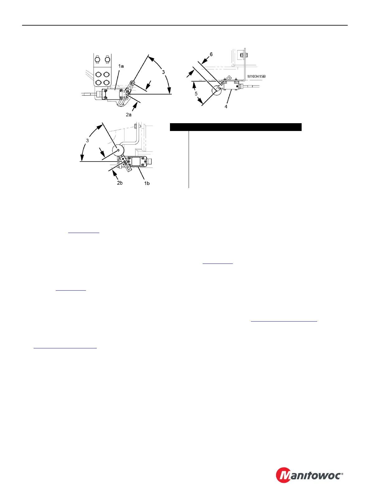
Positioning the Limit Switch Levers
The limit switch levers are positioned at the dimensions and
angles shown in Figure 6-11
at Manitowoc and should not
require further adjustment.
If a new limit switch is installed, the corresponding lever must
be positioned at the dimension and angle shown prior to
installation.
Adjusting the Beam Up Limit Switches
See View B, Figure 6-12 for the following procedure.
1. Slowly raise the VPC-MAX beam (2) with the assist
crane to the dimension (3): 10 mm (13/32 in) between
the underside of the rotating bed pins (4) and the bottom
of the beam hooks (5).
2. At the specified dimension, both beam up limit switches
(6) should trip (click) open. The beam up icons in
Figure 6-9 on page 6-12
should be tripped.
3. If necessary, adjust the position of the brackets (7) so
the beam up limit switches trip open at the specified
dimension (3).
4. Securely tighten the bracket mounting bolts.
Adjusting the Beam-on-Hook Limit Switches
See Figure 6-12 for the following procedure.
1. Slowly lower the VPC-MAX beam (2) with the assist
crane to the dimension (8): 10 mm (13/32 in) between
the top of the rotating bed pins (4) and the top of the
beam hooks (5).
2. At the specified dimension, both beam-on-hook limit
switches (9a or 9b) should trip (click) open. The beam-
on-hook icons in Figure 6-9 on page 6-12
should be
tripped.
3. If necessary, adjust the position of the brackets (10 or
11), so the beam-on-hook limit switches trip open at the
specified dimension (7).
4. Securely tighten the bracket mounting bolts.
Item Description
1a Beam-on-Hook Limit Switch (qty 2) PAST
1b Beam-on-Hook Limit Switch (qty 2) CURRENT
2a 50,8 mm (2 in) PAST
2b 56,0 mm (2-7/32 in) CURRENT
3 60° Angle
4 Beam Up Limit Switch (qty 2)
5 45° Angle
6 32 mm (1-1/4 in)
FIGURE 6-11
PAST
CURRENT