Manitowoc Published 04-06-18, Control # 231-14 6-19
MLC650 VPC-MAX™ OPERATOR MANUAL MAINTENANCE
Checking the Tray In and Out Limit Switches
See Figure 6-14 for the following procedure.
For this procedure, the actuator must be at the minimum
working position (Figure 6-10
) and the beam hooks must be
resting on the pins.
1. Verify that both tray limit switch levers are installed
perpendicular to the limit switch housings.
2. Using the remote control, travel the tray IN until the tray
IN tripping plate (2, View A) trips (clicks) open the tray IN
limit switch (3).
The tray should be at the dimension (4, View B): 235 mm
(9-1/4 in) between the angled edge of the roller path (4a)
and the front edge of the tray (4b).
If necessary adjust the limit switch mounting bracket (5)
so the limit switch trips open at the specified dimension.
3. In the main display (Figure 6-9 on page 6-12
), the tray
IN icon should be tripped.
If the icon indicates that the limit switch is NOT
TRIPPED, troubleshoot the electric control system and
fix the problem.
The tray IN limit switch must TRIP open when it
contacts the tray IN tripping plate.
4. Using the remote control, travel the tray OUT until the
tray OUT tripping plate (6) trips (clicks) open the tray
OUT limit switch (7).
The tray should be at the dimension (8, View B): 172 mm
(6-25/32 in) between the rear edge of the tray (8a) and
the angled edge of the roller path (8b).
If necessary adjust the limit switch mounting bracket (9)
so the limit switch trips open at the specified dimension.
5. In the main display (Figure 6-9 on page 6-12
), the tray
OUT icon should be tripped.
If the icon indicates that the limit switch is NOT
TRIPPED, troubleshoot the electric control system and
fix the problem.
The tray OUT limit switch must TRIP open when it
contacts the actuator OUT tripping plate.
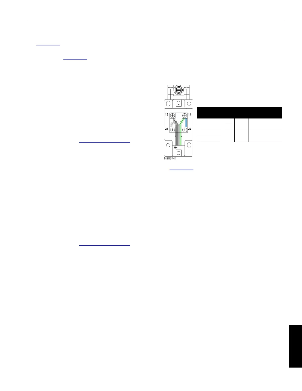
WIRING THE VPC-MAX LIMIT SWITCHES
See Figure 6-15 for wiring of the following limit switches:
• Beam-on-Hook (qty 2)
• Beam Up (qty 2)
• Actuator IN
• Actuator OUT
• Tray IN
• Tray OUT
VPC AND VPC-MAX ROLLER PATH
Prior to using the crane each day, inspect the VPC and VPC-
MAX roller paths on the rotating bed and the beam for
obvious obstructions and/or signs of damage. Remove the
obstructions. Contact the Manitowoc Crane Care Lattice
Team for inspection and repair criteria.
Limit Switch Wiring
Wire Color
Switch
Terminals
Function
Black 13 Normally Open
Green 14 Input
White 21 Normally Closed
Blue 14 22 Jumper
FIGURE 6-15