Manitowoc Published 04-06-18, Control # 231-14 4-7
MLC650 VPC-MAX™ OPERATOR MANUAL SET-UP AND INSTALLATION
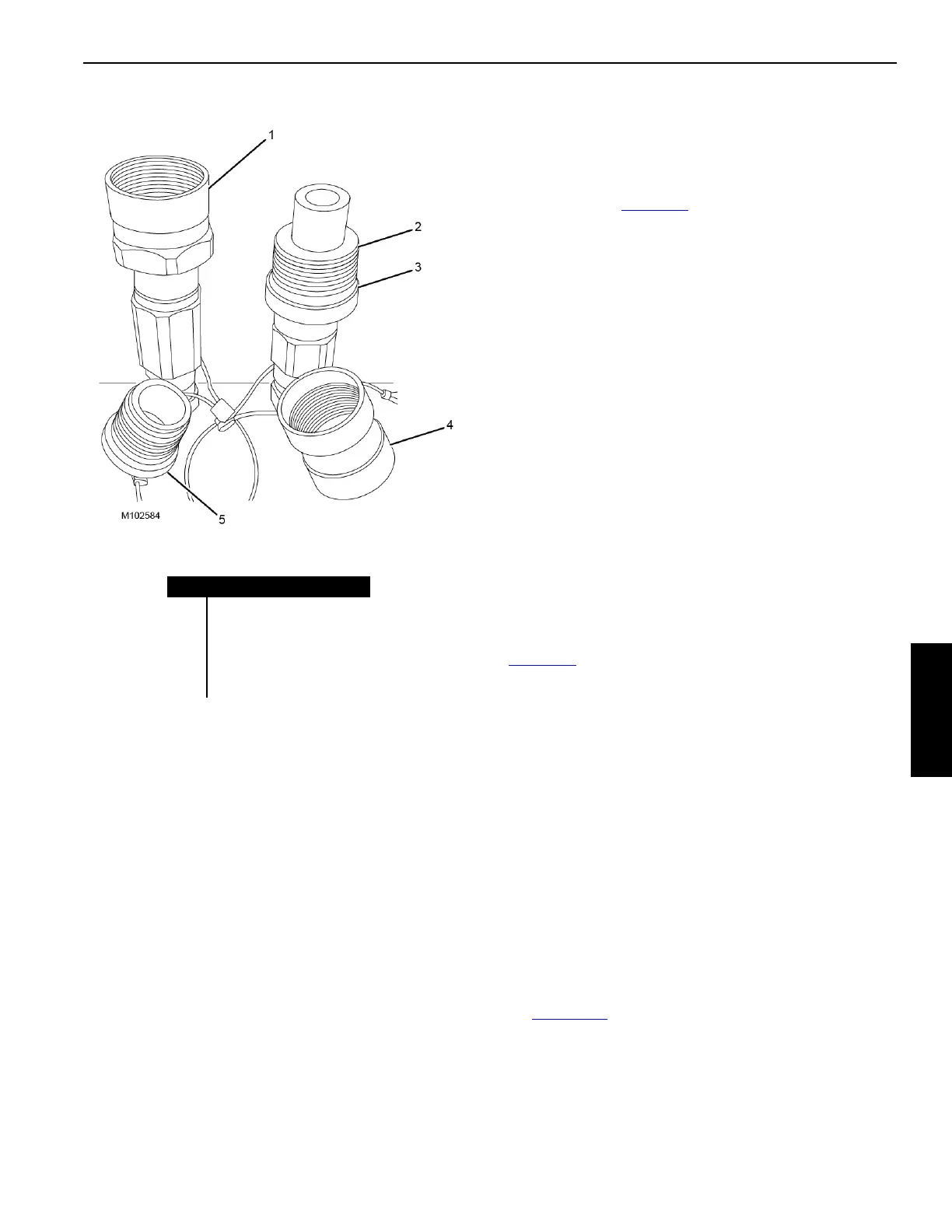
HYDRAULIC QUICK DISCONNECT
LUBRICATION
All hydraulic quick disconnects must be protected by
applying LPS-2 Aerosol Lubricant. Lubricant must be applied
while connecting and disconnecting the hydraulic quick
disconnects during crane assembly and disassembly.
1. All Quick Disconnects must be fully screwed together
until there is metal to metal contact during crane
assembly.
2. All plugs, regardless of location, must be fully screwed
together into their corresponding caps until there is
metal to metal contact during crane assembly.
Examples of locations of caps and plugs:
• Hanging lanyards
• Storage brackets
• Job box
3. All Quick Disconnects must be fully screwed together
with their corresponding cap and plug until there is metal
to metal contact during crane disassembly.
The following threaded areas of the quick disconnects, caps,
and plugs must be lubricated during crane assembly and
disassembly (see Figure 4-8
):
• Threaded surface of male quick disconnect
• Threaded surface of female quick disconnect
• Threaded surface of aluminum caps and plugs
• O-rings
NOTE: If the crane is stored without operating for long
duration, the hydraulic quick disconnects, caps,
and plugs must be lubricated every 6 months.
PIN AND CONNECTING HOLE
CLEANLINESS
To prevent dirt from damaging closely machined surfaces of
pins and connecting holes, perform the following tasks each
time the pins are installed:
• Thoroughly clean all pins and connecting holes.
• Apply a light coat of grease to all pins, contacting
surfaces, and connecting holes.
TIGHTENING HYDRAULIC COUPLERS
Connect each screw-to-connect coupler and nipple
(Figure 4-8
), as follows:
1. Lubricate coupler internal threads (1), nipple threads (2),
and nipple O-ring (3) with LPS-2 Aerosol Lubricant.
2. Hand tighten the coupler on the nipple.
3. Using opened-end wrenches from the parts box, tighten
the coupler until there is metal-to-metal contact between
the coupler and the nipple. Nipple o-ring must not be
visible.
To avoid damage, do not exceed a torque of:
• Size -06 = 2,2 Nm (1.62 lbf ft)
• Size -08 = 1,8 Nm (1.33 lbf ft)
• Size -12 = 5,6 Nm (4.13 lbf ft)
• Size -20 = 8,2 Nm (6.04 lbf ft)
• Size -24 = 26,0 Nm (19.16 lbf ft)
4. Check that the hydraulic tank shut-off valve (see
Figure 4-15
) is open.
Check for leaks after the crane has been operated with the
hydraulic oil at operating temperature. Retighten the
couplers if necessary.
Item Description
1 Female Quick Disconnect
2 Male Quick Disconnect
3O-ring
4 Aluminum Cap
5 Aluminum Plug
FIGURE 4-8