Manitowoc Published 04-06-18, Control # 231-14 4-67
MLC650 VPC-MAX™ OPERATOR MANUAL SET-UP AND INSTALLATION
6. Attach the SL 6 slings (2, View A) to the shackles on the
equalizer (3, View A) and to the lifting lugs (4, View A)
on the 12M insert (5, View A).
7. Assemble the partial boom to the crane using the fixed
mast (6, View A).
• See Section 4 of the Crane Operator Manual for
boom butt to crane pinning instructions.
8. Lower the partial boom onto the blocking (7, View B) that
is at least 610 mm (24 in) high and disconnect the slings
from the insert.
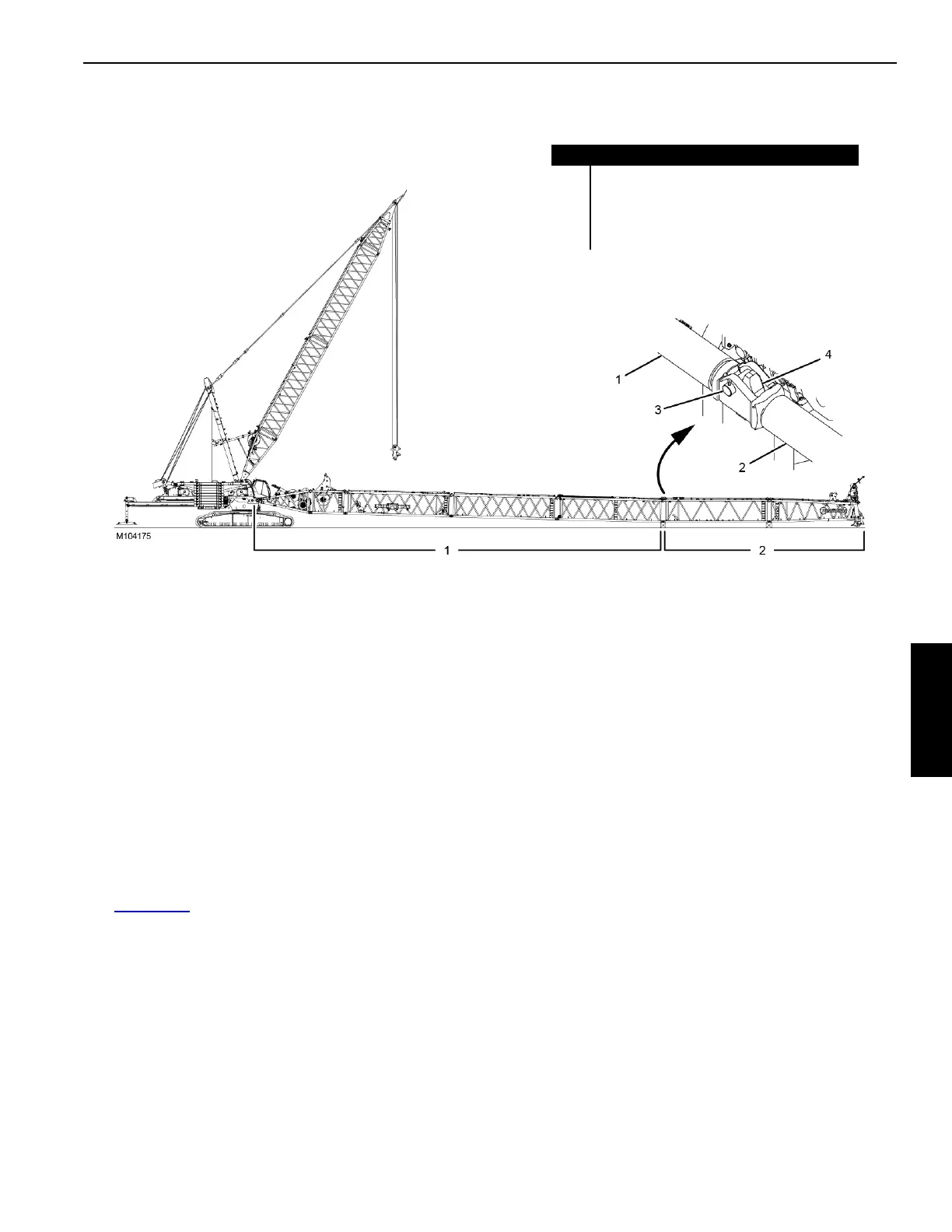
Assembling the Remaining Boom Sections
See Figure 4-60 for the following procedure.
Using an assist crane, assemble the remaining boom
sections (2) to the end of the partial boom (1).
• Block the boom sections at least 610 mm (24 in) high to
allow for installing the boom top.
• To prevent damage to the boom sections caused by
excessive sag, space the blocking at the intervals
specified under “Intermediate Blocking” requirement in
the Boom Rigging Drawing at the end of this section.
• See the Assemble Boom Inserts and Top topic in
Section 4 of the Crane Operator Manual for instructions.
• The inserts must be assembled in the sequence shown
in the Boom Rigging Drawing at the end of this section.
Connecting the Boom Straps
Starting at the boom top, connect the boom straps between
all of the boom sections to include the 12 m (39.4 m) straps
on the inserts with equalizer rails.
• See the Connect Boom Straps topic in Section 4 of the
Crane Operator Manual for instructions.
FIGURE 4-60
Item Description
1 Partial Boom (#680 or #685-680)
2 Remaining Boom Sections (inserts and top)
3 Fixed Horizontal Pin (qty 2)
4 Hooked Connector (qty 2)