Manitowoc Published 04-06-18, Control # 231-14 4-141
MLC650 VPC-MAX™ OPERATOR MANUAL SET-UP AND INSTALLATION
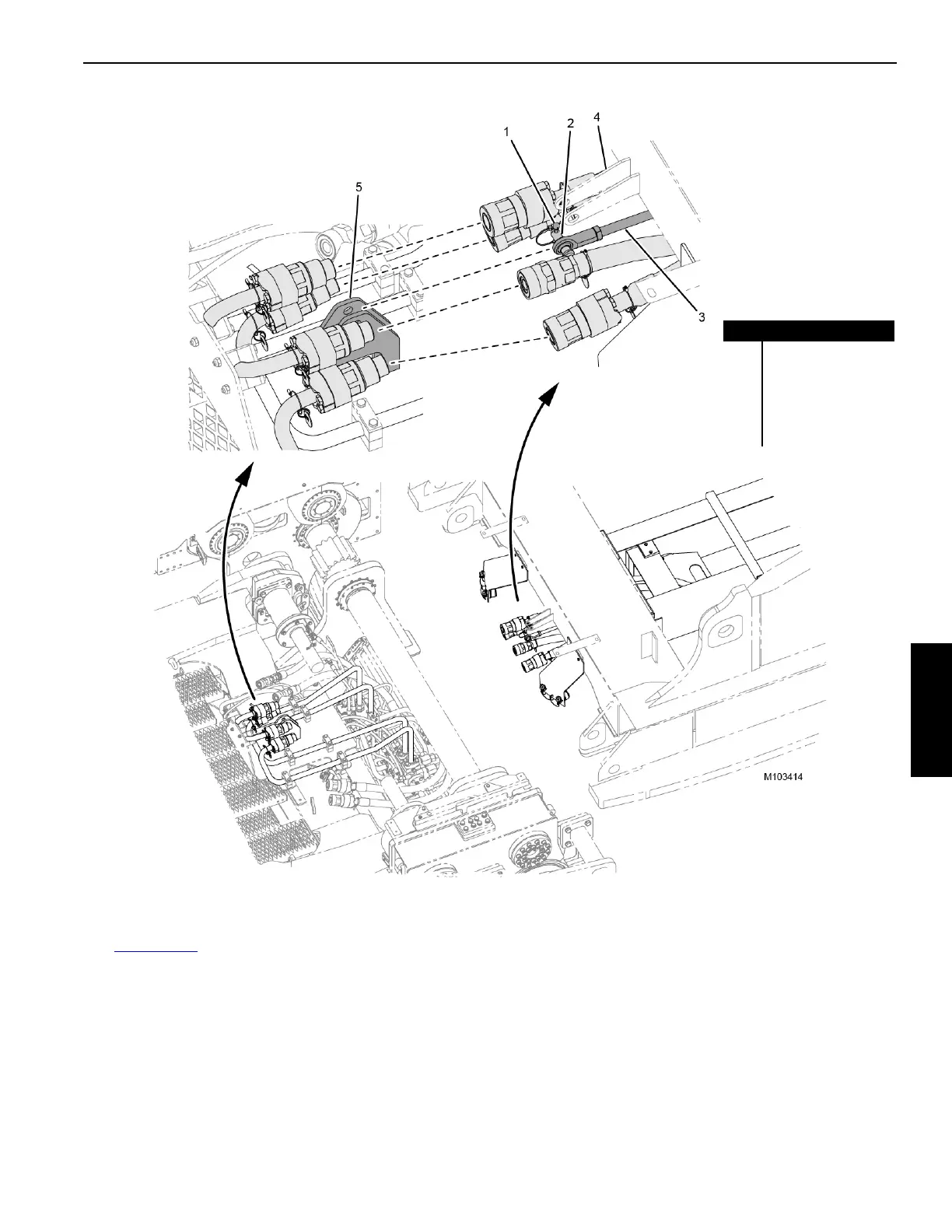
Detaching the Connecting Link
See Figure 4-118 for the following procedure.
1. Remove the locking pin (1) and retaining pin (2) from the
connecting link (3).
2. Remove the connecting link from the working position in
the actuator bracket (5).
3. Adjust the slide and/or tray position to align the
connecting link with the rotating bed bracket (4).
4. Install the retaining pin and hair pin cotter to secure the
connecting link in the stored position in the rotating bed
bracket.
FIGURE 4-118
Item Description
1 Locking Pin
2 Retaining Pin
3 Connecting Link
4 Rotating Bed Bracket
5 Actuator Bracket