Manitowoc Published 04-06-18, Control # 231-14 4-39
MLC650 VPC-MAX™ OPERATOR MANUAL SET-UP AND INSTALLATION
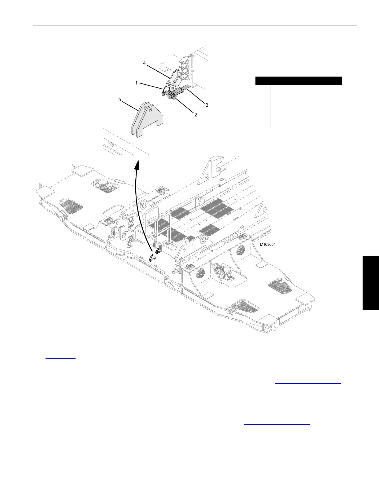
Attaching the Connecting Link
See Figure 4-37 for the following procedure.
1. Remove the locking pin (1) and retaining pin (2) from the
connecting link (3).
2. Remove the connecting link from the stored position in
the VPC-MAX beam bracket (4).
3. Adjust the slide and/or tray position to align the
connecting link with the counterweight tray bracket (5).
4. Install the retaining pin and hair pin cotter to secure the
connecting link in the working position.
Installing the Large Main Stop Blocks
1. Drive the tray forward to a position to allow for large
main stop block installation.
2. Install the large main stop blocks by reversing the
removal procedure (see Figure 4-34 on page 4-36
).
Detaching the Assist Crane
1. Detach the counterweight tray from the assist crane.
2. Store the pendants and plates in the counterweight tray
as shown in Figure 4-33 on page 4-34
.
FIGURE 4-37
Item Description
1 Locking Pin
2 Retaining Pin
3 Connecting Link
4 VPC-MAX Beam Bracket
5 Counterweight Tray Bracket