SET-UP AND INSTALLATION MLC650 VPC-MAX™ OPERATOR MANUAL
4-8
Published 04-06-18, Control # 231-14
SETUP MODE
To operate in the setup mode during crane assembly and
disassembly, the live mast must be configured in the RCL/
RCI display.
See the MLC650 RCL/RCI Display Operation Manual for
instructions.
This allows the boom control handle to raise and lower the
live mast and the right drum control handle to extend and
retract the self-erect cylinder.
AUXILIARY HYDRAULIC SYSTEM
Before using the hand-held pin puller the auxiliary hydraulic
system must be activated. This function increases the
accessory system pressure so the hand-held pin puller can
be connected and used.
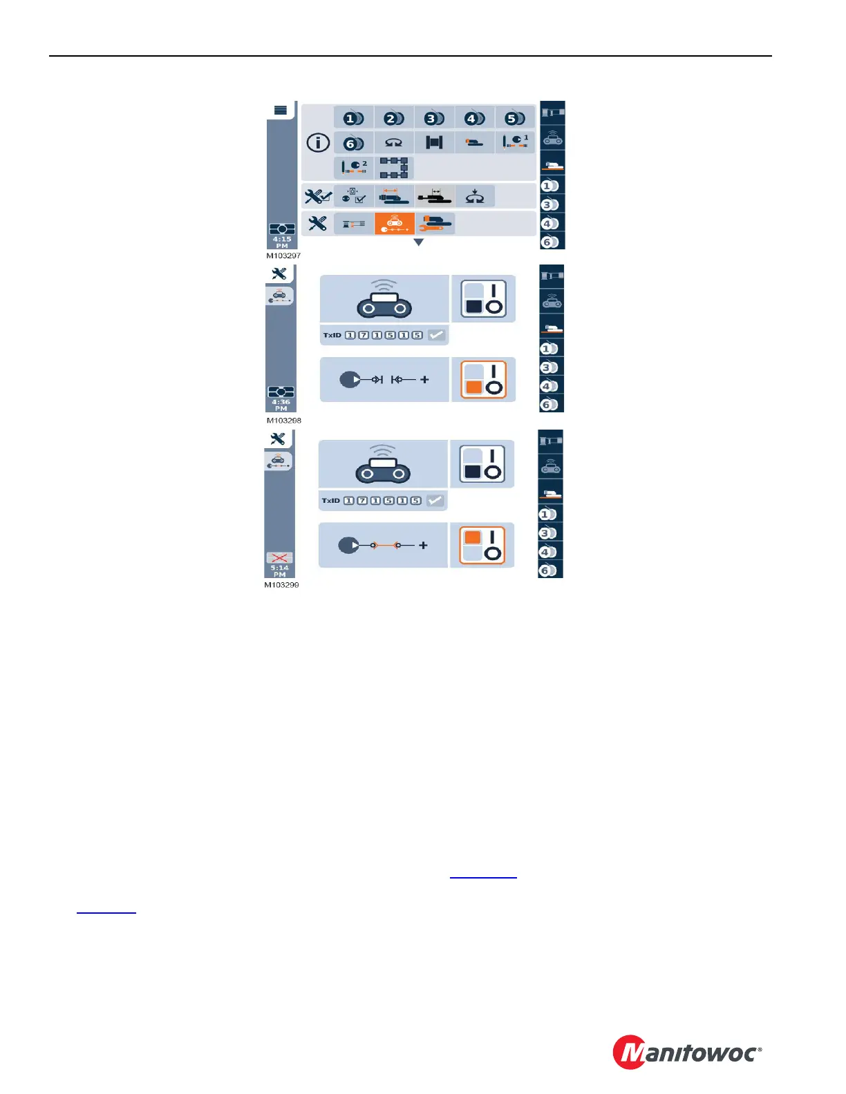
See Figure 4-9
for the following procedure.
1. Start from the first menu screen and use either the jog
dial on the right console, or the scroll keys on the display
to select the auxiliary hydraulics icon.
2. From the auxiliary hydraulics screen, scroll to the ON/
OFF (“I” or “O”) in the selection box.
3. Touch the OK button on the jog dial or display to select
the highlighted mode.
The screen changes to reflect the new mode.
HAND-HELD PIN PULLER
Use the hand-held pin puller to assist in the installation and
removal of the pins on the boom butt, live mast hoist (drum
4), gantry, backhitch, boom hinge, and the boom inserts.
See Figure 4-10
for the following procedure.
1. Locate the two hydraulic connections (2), found on the
rotating bed frame (1), and connect the two hydraulic
hose connections.
NOTE: The hydraulic connections can be found on both
sides of the rotating bed.
FIGURE 4-9
AUXILIARY HYDRAULICS
NOT ACTIVATED
FIRST MENU SCREEN
AUXILIARY HYDRAULICS
ACTIVATED