Manitowoc Published 04-06-18, Control # 231-14 4-43
MLC650 VPC-MAX™ OPERATOR MANUAL SET-UP AND INSTALLATION
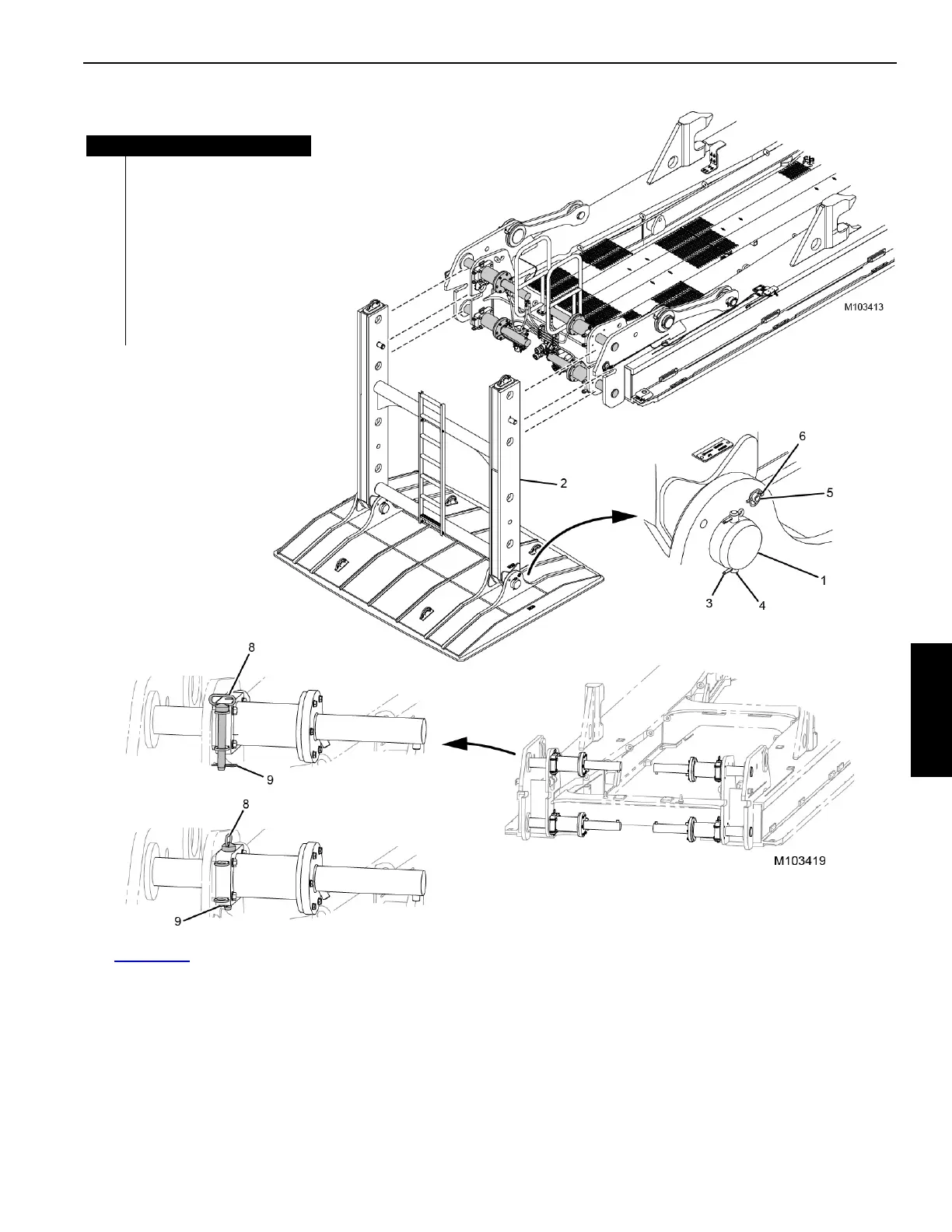
See Figure 4-40 for the following procedure.
9. Install the clevis pins (1) to the auxiliary frame
assembly (2).
10. Install the retaining pins (4) to the clevis pins.
11. Secure the retaining pins with the cotter pins (3).
12. Install the secondary pins (5).
13. Secure the secondary pins with the lynch pins (6).
14. Using the assist crane, install the auxiliary frame
assembly in its working position.
15. Using the remote control, extend the powered retaining
pins (7).
16. Remove the hitch pins (8) from the stored position.
17. Install the hitch pins and the hair pin cotters (9) in the
working position.
FIGURE 4-40
Item Description
1 Clevis Pin (qty 2)
2 Auxiliary Frame Assembly
3 Cotter Pin (qty 8)
4 Retaining Pin (qty 4)
5 Secondary Pin (qty 2)
6Lynch Pin (qty 4)
7 Powered Retaining Pin (qty 4)
8Hitch Pin (qty 4)
9 Hair Pin Cotter (qty 4)
STORED POSITION
WORKING POSITION