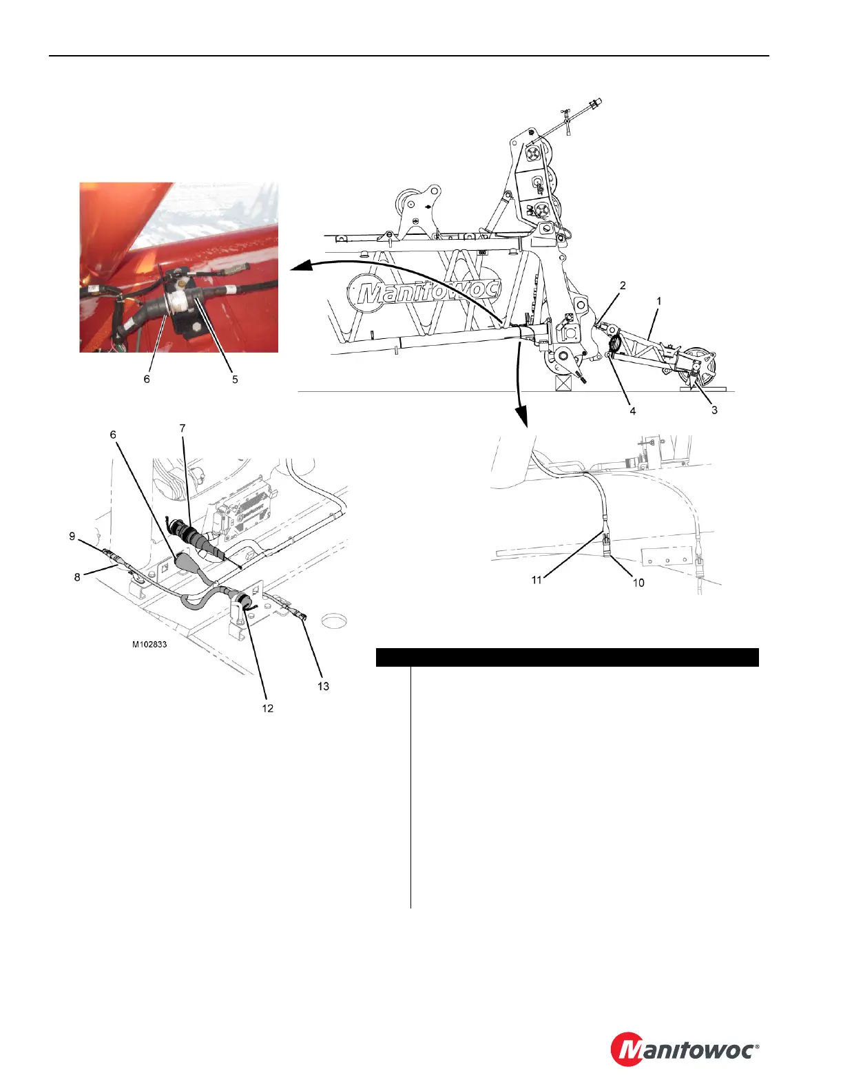
FIGURE 4-67
Item Description
1 Upper Boom Point
2 Pin with Safety Pins (qty 2)
3 Anti-two Block Lug
4 Pin with Safety Pins (qty 2)
5 Electrical Cable (WBU1-P1 connects to WBT1-J2)
6 Receptacle (WBT1-J2 ATTACHMENTS)
7 Shorting Plug
8 Electrical Cable (WBT1-J6 — CAN NET OUT)
9 Terminator Plug
10 Shorting Plug
11 Electrical Cable - SLOW DOWN (optional)
12 Electrical Cable (WBT1-J1 — POWER from boom cable reel)
13 Electrical Cable (WBT1-J5 — CAN NET IN from boom cable reel)
View A
View B