TECHNICAL DATA11 - 4
D-MAXE with OI-TS www.maxcessintl.comMI 2-292 1 C
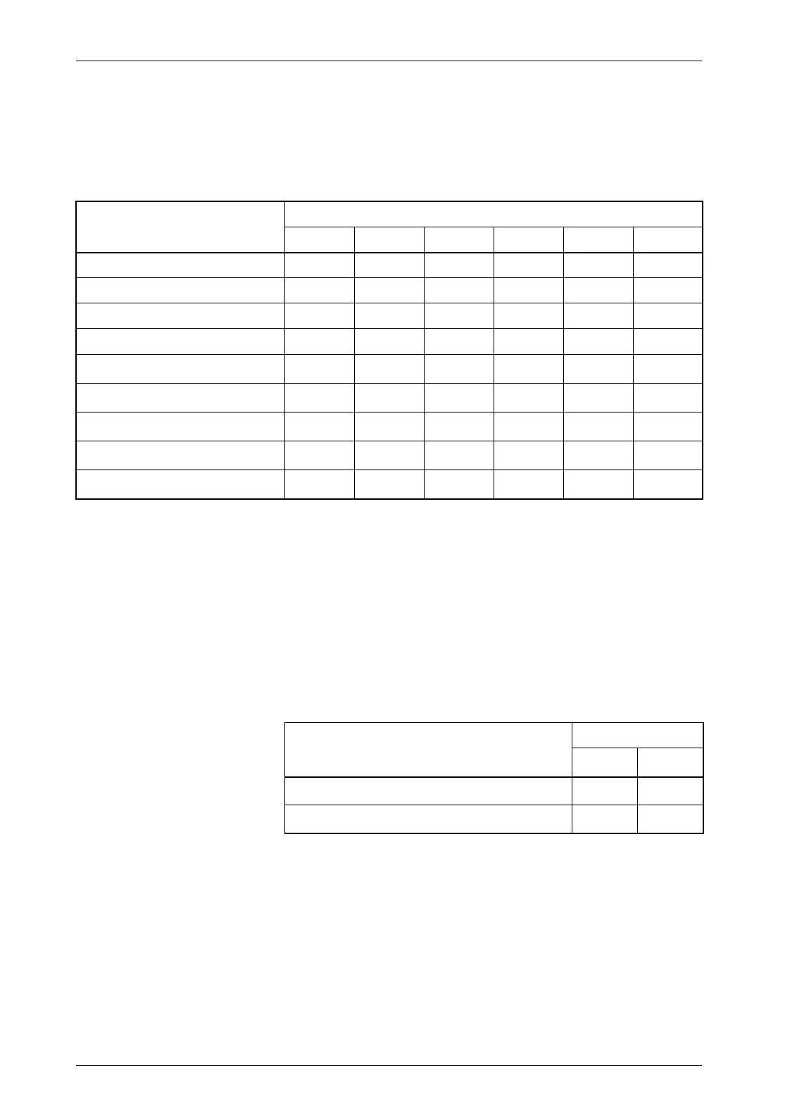
Parallel input matrix Because of the option for customer-specific programming, there
may be some deviations in the parallel input matrix. Customer-
specific software adjustments of this type are described in the
"Supplementary Operating Instructions" for the D-MAXE system
and are included in the system documentation.
L = Low level (<= 0,9V or blank)
H = High level (3,6V - 24V)
Empty field = not relevant for the specific command
* Inputs 4 and 5 for moving the drive in "Manual" and "Servo
Center" modes
Offset of the guide point (RGPC) in "Automatic" mode
Parallel output matrix
The menu
1y.5.4 Digital Outputs, page7-17
can be used to
adjust the assignment of the logical state (1 or 0) to the
electrical state (active low, active high, high-impedance).
If there are differences compared to the table, they are
described in the "Supplementary Operating Instructions" in the
system documentation.
Mode
Inputs
543210
Locking, external -----H
Automatic - - L L H -
Manual - - L H L -
Servo Center - - H L L -
Move drive left
*
LH----
Move drive right
*
HL----
RGPC left
*
LH----
RGPC right
*
HL----
RGPC RESET
*
HH----
Status
Outputs
B
*
A
*
LOSS OF NULL (Automatic mode) - 1
Drive servo-centered (Servo-Center mode)
1-