33
2.1.4.5 Parameter settings for EtherCAT network connection
To use MV810-ECAT02 to operate the MV800 series drive, you need to set the operation command channel and
frequency source to the bus communication card, as shown in the following table.
Table 2-8 Parameter settings for MV810-ECAT02 communication
Set the operation command channel to communication control
Set the communication command channel to EtherCAT
Set the main frequency source to bus card (EtherCAT)
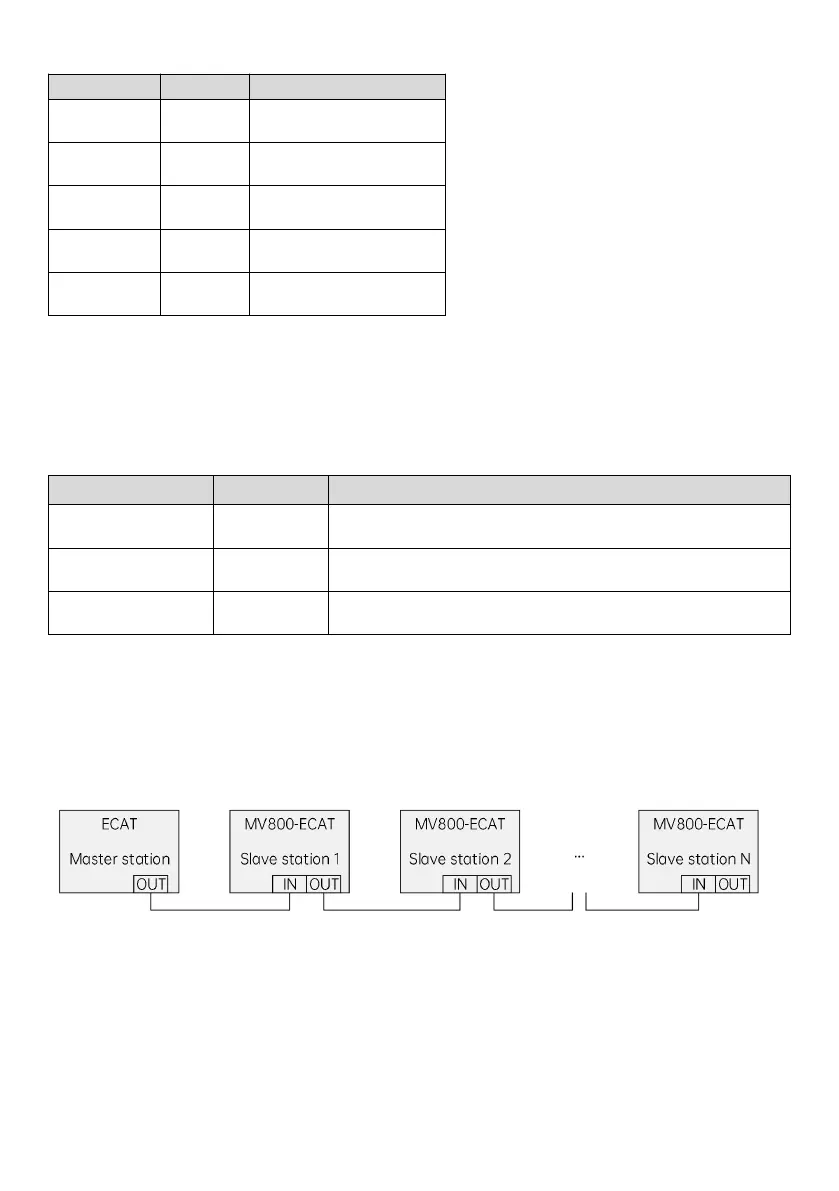
2.1.4.6 Network topology
EtherCAT network is generally composed of a master station and multiple slave stations. The network structure can be
divided into the bus type, star type, tree type, etc., or the combination of several types, realizing flexible device
connection and wiring. The bus-type network topology is shown in the figure below.
Fig. 2-11 ECAT bus connection
2.1.4.7 LED indicator description and fault diagnosis
MV810-ECAT02 has five LED indicators: the LEDs on the PCBA of the expansion box and the LED on the communication
port. The LED on the PCBA indicates the function status and power status; and the LED on the communication port
indicates whether the communication status of MV810-ECAT02 is normal.
 Loading...