FOCKE MELER GLUING SOLUTIONS
3-4
INSTALLATION
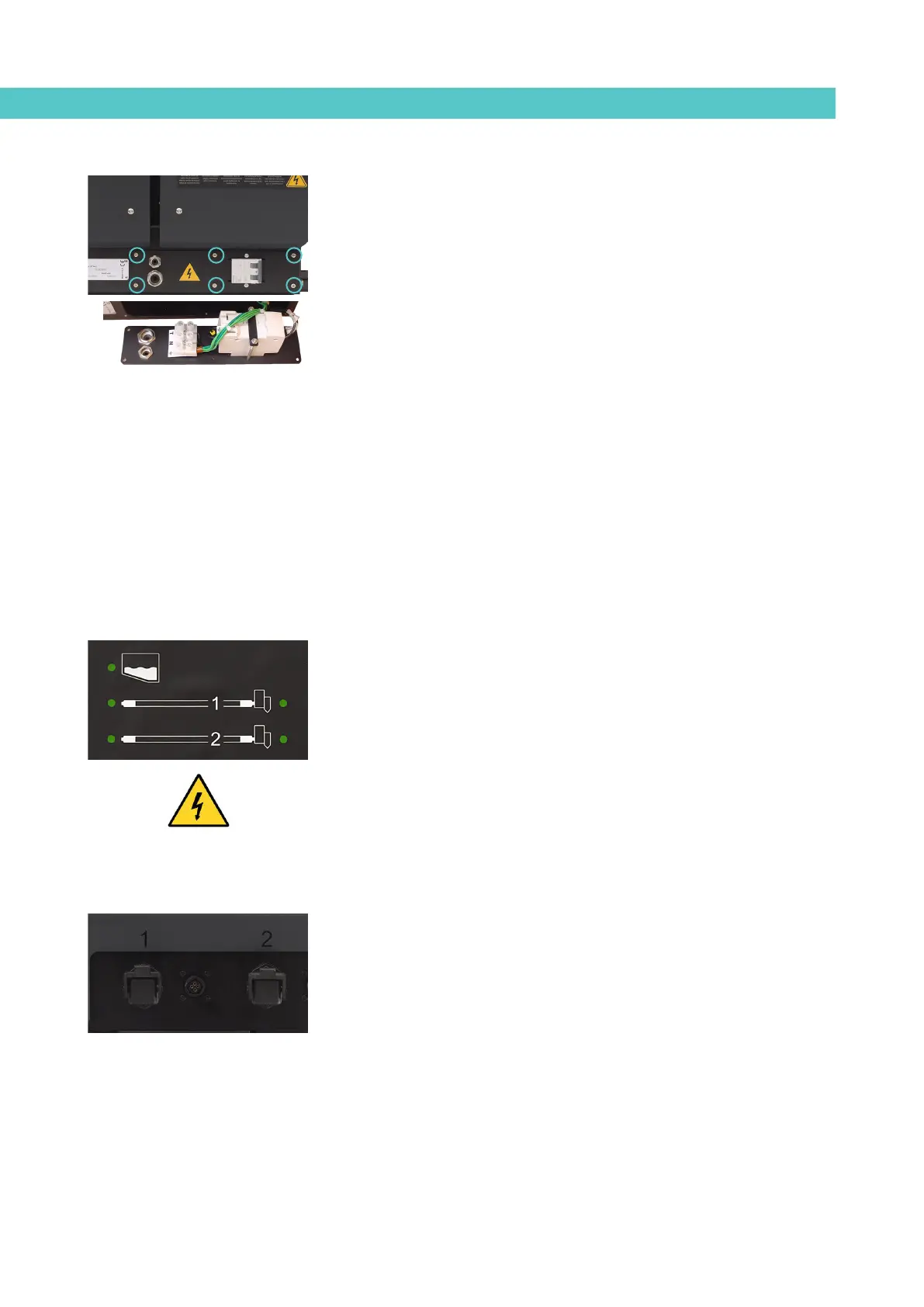
Remove the six screws fastening the connection support plate and power
switch, on the left side of the equipment. Pass the power cable (Ø6-12 mm)
through the Pg13 bushing and fasten as shown in the figure, ensuring that the
cable is perfectly secure and that it does not impede the mounting of the plate.
Connect each of the power cable’s wires in their corresponding position in the
input terminals.
Pneumatic connection
Before connecting the pneumatic supply to the air drying system or to the
bypass valve (optionals), ensure that the pressure regulators are fully closed.
To do this, turn both regulators control anti-clockwise.
Connect the plant’s air supply (6 bar max.) to the equipment input using a
flexible tube with an outer diameter of 6 mm. The melter has a quick release
coupling for this purpose.
Allow the air to flow and turn the pressure regulator clockwise until the
desired pressure is reached.
Hose and applicator connection
The B4 VS melter can use standard Meler components. The entire range of
Meler hoses and applicators may be connected to this equipment.
The B4 VS melter has two outputs for connecting the hose-applicator for only
one installed pump. These are identified on the same plate with the numbers
1 and 2. These numbers correspond to the control channels which appear on
the front control panel.
Warning: When connecting the hose-applicator outputs, check that the power
connected does not exceed the maximum power allowed.
Caution:
• To identify each hose-applicator pair, electrically connect them to the
connector with the same number as the output used.
• It is preferable to use couplings at 45° or 90° to minimise the space
occupied by the hose. Straight couplings usually generate very small
radii of curvatures that may damage the inside of the hose.
• Save the threaded cap which is removed from the distributor when
connecting the hose. It may be required in the future if the hose is
removed from its position.
• Electrically connect the hose and applicator when the equipment
is turned off. Failing to do so may result in electrical defects in the
connection and alarm messages may appear on the melter display.