4-21
MELTER OPERATION MA-5082-ENG B4 VS ADHESIVE MELTER MANUAL
• To reset this error, you must turn off and start up the control card with
its ON/OFF button.
Variator alarm
This alarm is triggered when the control card input is activated by a variator
error signal.
• When this alarm is triggered, an ‘E.U.’ error is shown on the control card.
• The error message will be maintained while the variator error input
(E5) remains active. As soon as this input is deactivated the alarm will
be reset.
Note: In the event that a RPM alarm and a variator ERROR alarm should
coincide, alternating messages will appear on the display.
Configuring speed ramp
For equipment operating in external reference, the display will show the
current pump rotation set point (input reference conversion as per the full
scale and the conversion table).
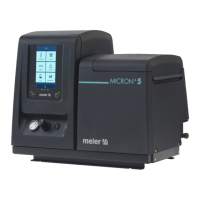
The conversion table may be programmed with up to 5 points (input voltage (V)
and output speed (RPM)).
By default the table is programmed (0 V = 0 rpm and 10 V = 100 rpm):
Notes on the editable values in the conversion table:
• The value for voltage must always be shown to one decimal place.
• Point 1 is the starting point for the speed ramp, and therefore the
voltage will always be 0, while the value for output RPM is editable.
• The possible values for each point must be equal to or greater than the
value corresponding to the previous point.
• Point 5 is the final point for the speed ramp, and therefore the voltage
will always be 10, while the value for output RPM is editable.
• It is not necessary to program the value for MAXIMUM RPM in this table.