3-7
INSTALLATION MA-5082-ENG B4 VS ADHESIVE MELTER MANUAL
• Motor start up_for each pump installed, the motor start up may be
controlled by closing an external non-voltage contact.
• Motor speed set point_for each pump installed, the rotational speed of
the motor (and therefore, the pump) may be controlled by means of a 0
to 10V DC external signal.
• Failures output in pump control card_output from a non-voltage
contact that communicates normally to a warning light beacon the
failure from the pump control card.
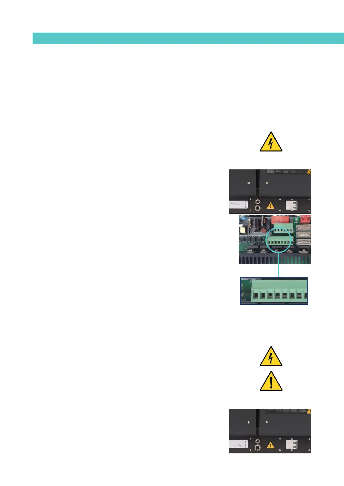
Warning: Risk of electric shock. Carelessness may cause injury or death.
Temperature ok
1. If only this signal will be connected, use a 0.5 mm
2
two-wire cable.
Install a Pg9 bushing on the equipment base plate, next to the electric
power supply unit.
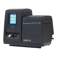
2. Remove the six screws fastening the connection support plate and
power switch, on the left side of the equipment. Pass the signal cable
(Ø4-8 mm) through the Pg9 bushing and attach it to the internal fitting,
ensuring that the cable reaches the control board connector at the
point where it is to be installed (CN4).
3. Remove the connector from the panel and connect the two cable wires
to their corresponding connector terminals:
1 contact NO
3 contact NO
4. Reconnect the connector to the panel.
5. Check that the cable is correctly connected and that its passage
through the electric cabinet presents no risk of jamming, being cut or
any other accidental damage.
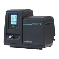
Warning: Connect to 24 V (AC or DC). If connected to 230 V the load current
cannot be less than 50 mA.
Note: take into account the image of CN4 temperature ok connector, do not
confused with CN4 external standby connector.
External standby
1. If only this signal will be connected, use a 0.5 mm
2
two-wire cable.
Install a Pg9 bushing on the equipment base plate, next to the electric
power supply unit.
1 3