3-9
INSTALLATION MA-5082-ENG B4 VS ADHESIVE MELTER MANUAL
Motor speed set point reference (ref ext)
1. If this is the only signal being connected, use 0.5 mm
2
two-wire cable.
Install an electrical wall bushing Pg9 on the equipment base plate next
to the electrical supply input.
2. Thread the power cord (max. Ø4-8mm) through the electrical wall
bushing Pg9 and fasten it to the inside anchor, making sure that the cord
reaches the power card connector.
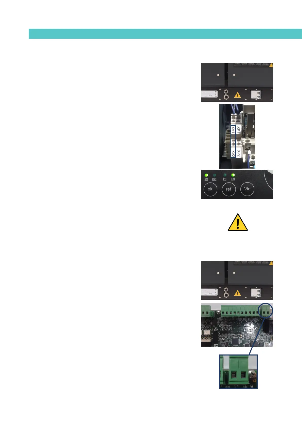
3. Connect the two wires from the start-up signal to the terminals XV1
and XV2. This is a double terminal, which makes it necessary to
connect each wire in one of the two holes in the terminal. The positive
signal wire must be connected to point XV2 of the terminal, while the
negative wire must be connected to point XV1.
4. Make sure that the cables are firmly attached by the terminal screws.
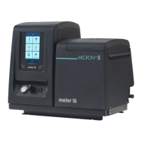
5. For the signal to work, the led ‘ref ext’ on the control panel must be on.
Warning: When connecting the 0-10V signal to the equipment. Make sure that
the signal is not inverted or the signal applied is not excessive (more than 10
volts). Connect to inappropriate voltage or a wrong installation can result in an
unpredictable behavior and even irreversible damage.
Failures output in pump control card
1. If this is the only signal being connected, use 0.5 mm
2
two-wire cable.
Install an electrical wall bushing Pg9 next to the electrical supply input.
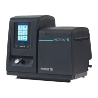
2. Remove the six screws fastening the connection support plate and
power switch, on the left side of the equipment. Pass the signal cable
(Ø4-8 mm) through the bushing Pg9 and attach to the internal fitting,
ensuring that the cable reaches the control board connector at the
point where it is to be installed (S4).
3. Remove the connector from the panel and connect the two cable wires
to their corresponding connector terminals:
1 contact NO
2 contact NO
4. Reconnect the connector to the panel.
1 2