MA-5162-ENG MICRON
+
PISTON ADHESIVE MELTERINSTALLATION
3-9
Connecting external inputs and outputs
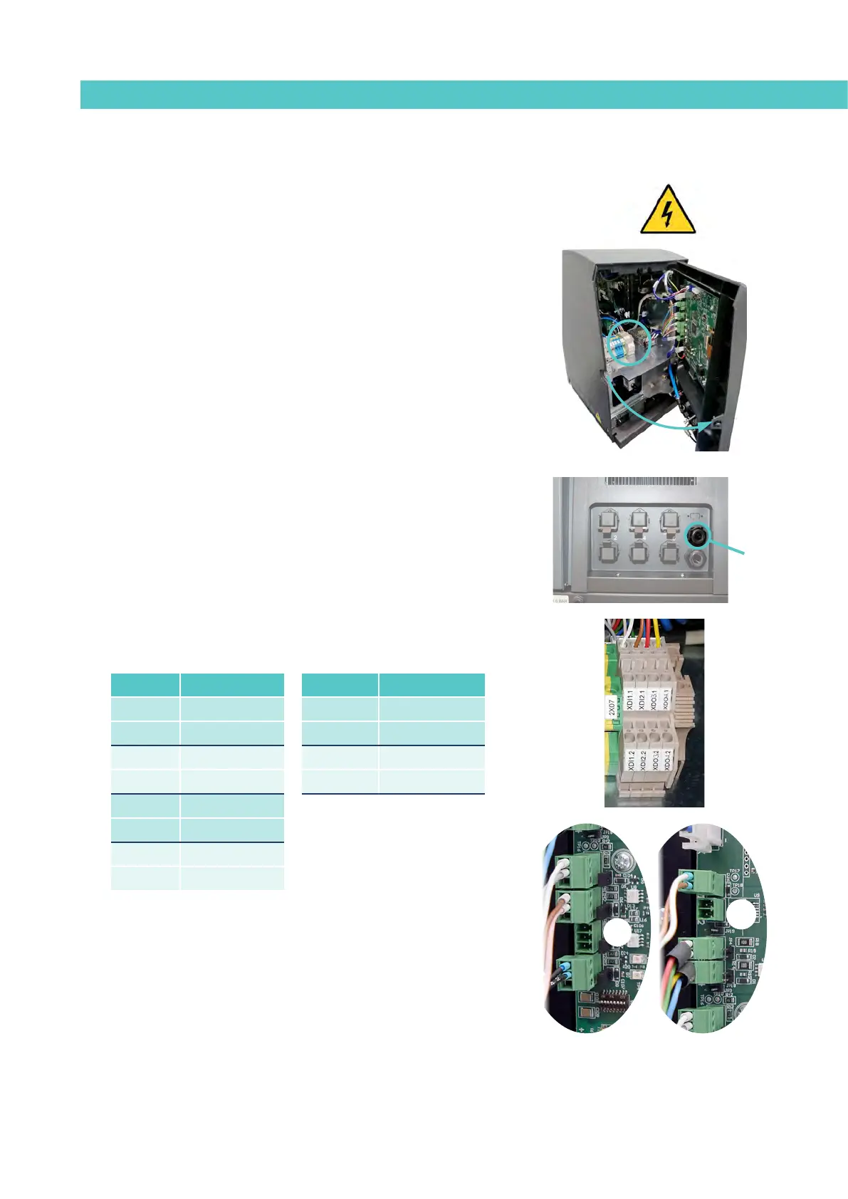
Warning: Risk of electric shock. Carelessness may cause injuries or death.
1. Disconnect the unit’s power.
2. Open the front door of the electric cabinet by giving the fastening
screw a 1/4 turn.
3. Run the signal cable (max. Ø14 mm) through the bushing at the rear
of the unit (P) and attach it to the interior fitting, making sure the
cable reaches the corresponding terminals/connectors.
4. Connect the two cable wires to the corresponding terminal/
connector. The polarity of the connection must be correct:
5. Make sure that the cables are properly secured by the terminal’s
screws.
6. Check that the cable is correctly connected and that its passage
through the electric cabinet presents no risk of jamming, being cut
or any other accidental damage.
7. To assign the function to be performed by the connected signal, see
point ‘4 Use / Settings Menu / Configuration of input and output
signals’’.
P
DI3
DO2
Terminal Polarity Connector Polarity
XDI 1.1 +24 VDC 200mA DI3 1 +24 VDC 200mA
XDI 1.1 IN DI3 2 IN
XDI 2.1 +24 VDC 200mA DO2 1 +24 VDC 2A
XDI 2.2 IN DO2 2 GND
XDO 3.1 +24 VDC 100mA
XDO 3.2 GND
XDO 4.1 +24 VDC 100mA
XDO 4.2 GND