CHARGING AND STARTING SYSTEM
Page 2B-34 90-828631R3 MARCH 1999
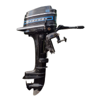
6. Place springs and brushes into brush holder and hold in place with brush retainer tool.
7. Lubricate bushing with one drop of SAE 10W oil. DO NOT over-lubricate
.
11661
b
a
a-Brush Retainer Tool
b-Bushing
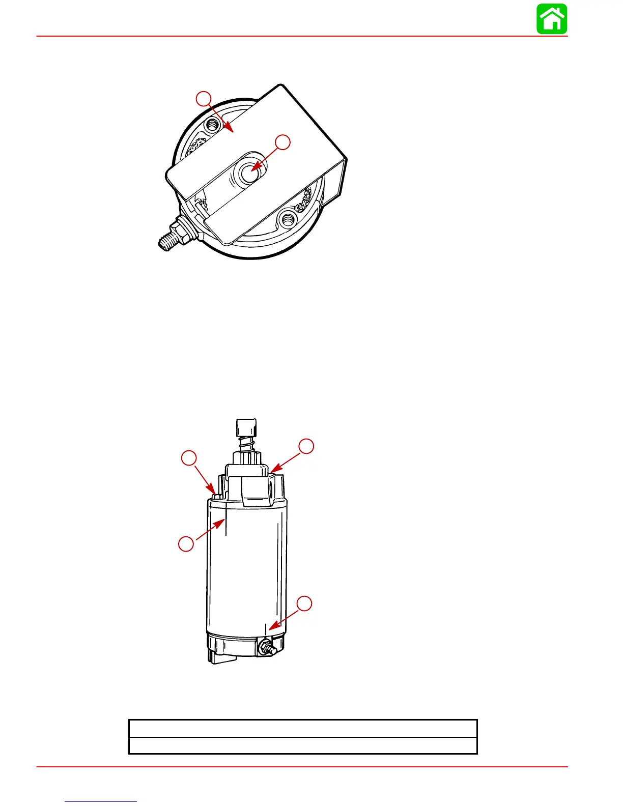
8. Position armature into starter frame so that commutator end of armature is at end of
starter frame where permanent magnets are recessed 1 in. (25.4mm). Align marks (a)
as shown.
9. Install commutator end cap onto starter frame; align marks (b) as shown, and remove
brush retainer tool.
10. Install thru bolts (c) and torque to specified torque
.
52659
a
b
c
c
a-Alignment Marks
b-Alignment Marks
c-Bolts (2)
End Cap Bolt Torque
70 lb-in. (7.9 Nm)

 Loading...