TILLER HANDLE
Page 7B-10 90-828631R3 MARCH 1999
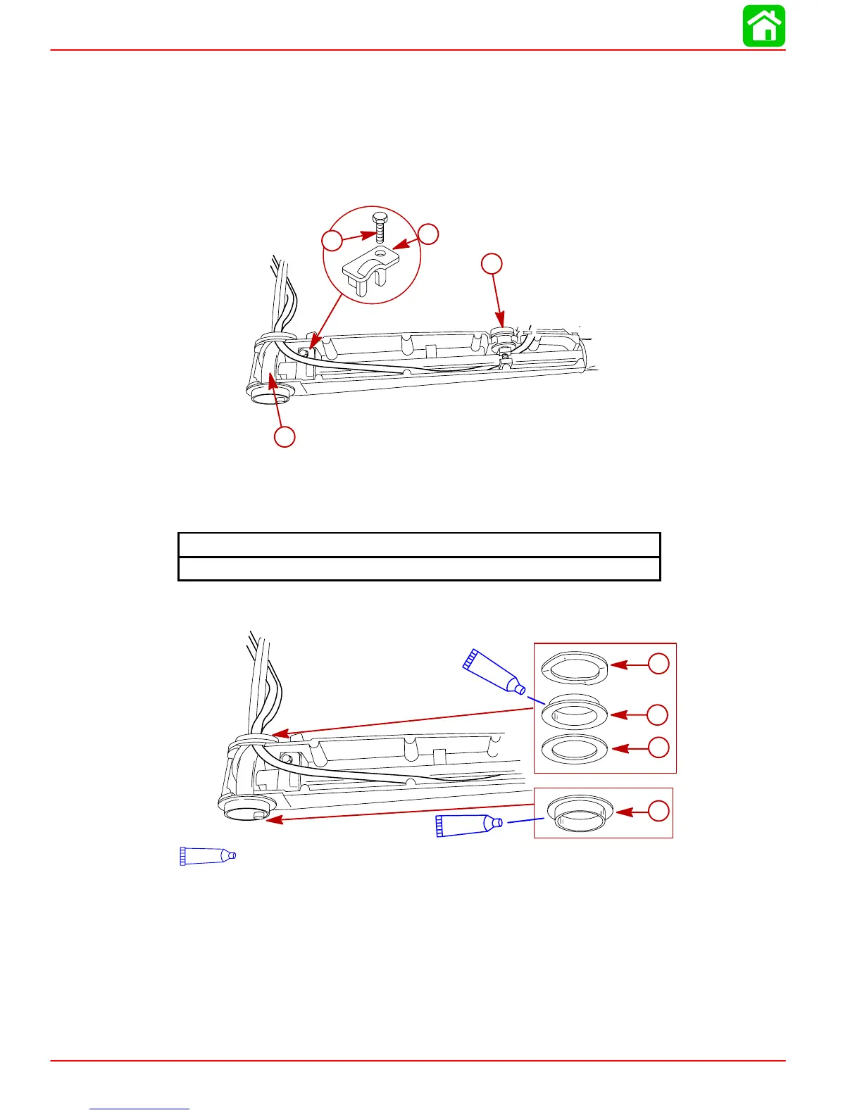
9. Place pulley assembly into arm.
10. Slide the tiller tube into the arm. Position the throttle lock knob into its slot.
11. Match the end of the tiller tube with the slots in the pulley assembly. Insert the tiller tube
end into the pulley assembly.
12. Secure tiller tube with retainer.
13. Snap the engine start switch on the tiller tube.
a
c
d
b
a-Pulley Assembly
b-Throttle Lock Knob
c-Retainer
d-Screw-M5x16
Tiller Tube Retainer Screw Torque
35 lb-in. (3.9 Nm)
14. Place bushing components on the arm mounts.
a
b
c
d
95
2-4-C w/Teflon (92-850736A1)
95
95
a-Flat Washer
b-Bushing
c-Wave Washer (2)
d-Bushing

 Loading...