TILLER HANDLE
90-828631R3 MARCH 1999 Page 7B-9
4. Match tiller tube end with the slots and pull the tube end into the handle until it bottoms
out.
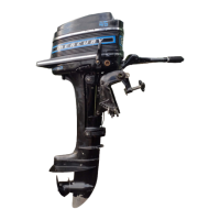
5. Install the throttle lock components on tiller tube.
a
b
c
c
d
e
f
g
a-Tiller Tube
b-Handle
c-Match the Tube End with Slots
d-Screw
e-Lock
f-Spring
g-Knob
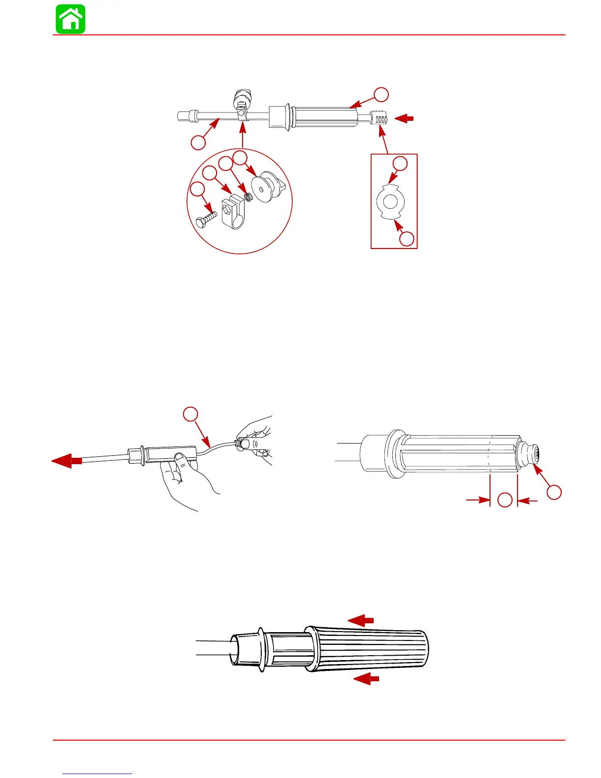
6. Check to make sure tiller tube is pushed in 7/8 in. (22.2mm).
7. Insert the engine stop switch harness through the tiller tube. Place the stop switch into
end on handle.
7/8 in. (22.2mm)
c
a
b
a-7/8 in. (22.2 mm) between Tiller Tube and end of Handle
b-Engine Stop Switch Harness
c-Stop Switch
8. Align the grooves inside the rubber grip with the ridges on the handle. Push the rubber
grip onto the handle.
NOTE: Applying a soapy/water solution to the inside of the rubber grip will ease installation.

 Loading...