Workstation 5 Field Service Guide 4-9
Remove and Replace the Workstation 5 FRUs
LCD/Touchscreen Procedures
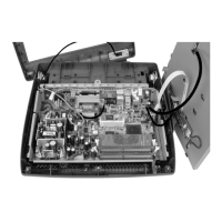
Figure 4-8 below, represents the standard Resistive LCD/Touchscreen
assembly showing the Backlight Inverter Board and interface cables. The
resistive touchscreen ribbon cable and inverter board interface cable terminate
on the system board.
Figure 4-8: LCD/Touchscreen Assembly with Resistive Touchscreen
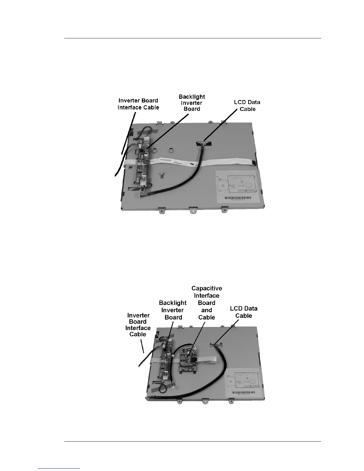
Figure 4-9 shows the rear of the LCD/Touchscreen assembly when the
capacitive touchscreen is installed. This configuration adds the Capacitive
Interface Board and interface cable. The touchscreen ribbon cable is connected
directly to the Capacitive Interface Board.
Figure 4-9: LCD/Touchscreen Assembly with Capacitive Touchscreen Option