2-22 Workstation 5 Field Service Guide
Workstation 5 System Board Technical Descriptions
AC 97 Audio Interface
The AC’97 architecture provides for data transfer through individual frames
transmitted in a serial data stream. A Time Division Multiplexed (TDM)
scheme is used to allow multiple input and output streams as well as access to
the internal control registers. Each frame is divided into 12 out going and 12
incoming data frames or slots.
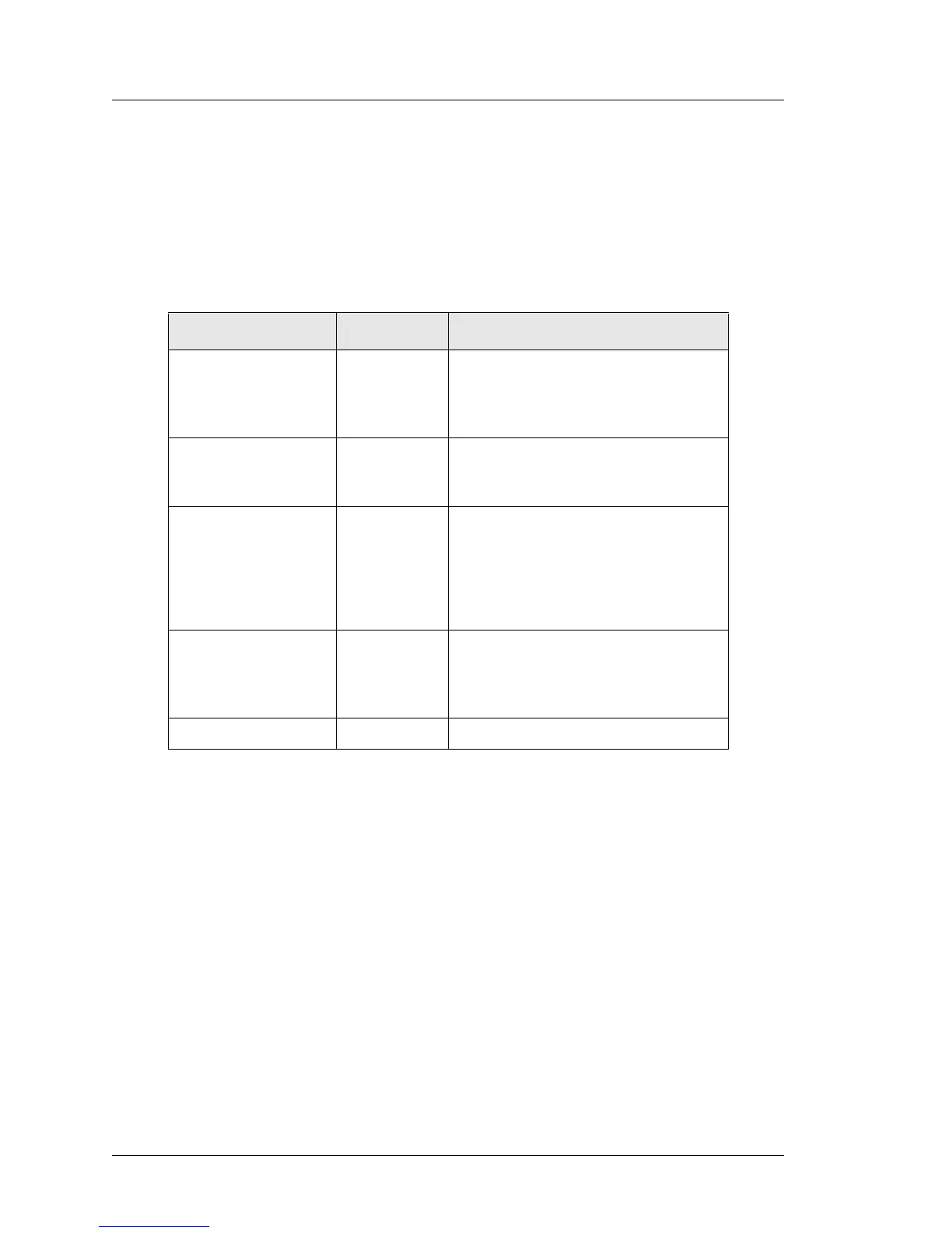
The Table below describes the function of each audio link signal at U9, the
audio codec.
Speaker and Line Outputs (REF: ABRD88, Sheet 28)
The speaker outputs of the codec drive U26, a LM4940 ‘Boomer’ series audio
amplifier. The LM4940 outputs, SPK_R_OUT and SRK_L_OUT drive system
board connectors CN9 and CN10 respectively. The speakers are mounted
internally, at the left and right sides of the case.
AUD_PWRON, from a GPIO pin on Super IO #1, is pulled to ground by R405
and fed to the SHUTDOWN input of U9. The BIOS sets AUD_PWRON low
during a warm or cold boot to reduce speaker ‘pop.’
The LINE_OUT_R and LINE_OUT_L outputs are fed through a low-pass filter
to Line Out Jack CN3. The internal speakers remain active when the Line-Out
jack is used.
Signal Name I/O Description
AC97_SYNC Input/Output 48 Khz sync pulse that indicates the
beginning of a serial transfer on
AC97_DATA_OUT and
AC97_DATA_IN.
AC97_BITCLK Output 12.888 Mhz Serial Data Clock from
the codec. Derived from the
CLK_14_CODEC input at Pin-2.
AC97_DATA_OUT Output Audio Controller Serial Data Out.
Transmits audio data to the codec.
Data stream consists of both control
data and audio data. Data valid on
rising the rising edge of
AC97_BITCLK.
AC97_DATA_IN Input Audio Controller Serial Data In. Data
stream consists of both control data
and audio data. Data valid on rising
the rising edge of AC97_BITCLK.
PCI_RST# Input Working Domain Master Reset.