Workstation 5 Field Service Guide 3-27
Workstation 5 Troubleshooting
Touchscreen Related
Touchscreen Related
This section includes several touchscreen related symptoms and applies only to
the ABRD88 system board. Note that a POST for the touchscreen interface and
controller is not implemented.
Touchscreen Not Responding after the Operating System Starts
Symptoms: The Workstation 5 starts Windows Embedded CE 6.0, but the
touchscreen does not respond. No error messages are reported.
• Restart the Workstation. Do not touch the screen until after the unit boots to
the CE Desktop.
o The current Windows Embedded CE 6.0 touch screen driver has a
known issue where if the user touches or cleans the touchscreen while
WinCE boots, it fails to detect touches after WinCE displays the
desktop.
• If the touchscreen does not function after allowing the system to boot
without touching the screen, see below.
o Defective, damaged, or pinched interface cable. Check the cable at the
point where it mounts to the glass surface.
o Defective touchscreen interface U17/U19.
o Damaged EMI Protection Circuit - Check D8 through D12.
Touchscreen Calibration
Symptoms: After booting, touches appear on the screen, but the calibration is
such that you cannot access the desktop calibration icon.
• Defective, damaged, or pinched interface cable. Check the cable at the
point where it mounts to the glass surface.
• Connect a USB Keyboard/Mouse combo and start the ‘TSHARC
Calibration’ utility on the desktop.
o Run through the calibration procedure, touching and holding each
target, and releasing when prompted. If touchscreen calibration is not
acceptable after completing the procedure, see below.
• Defective Touchscreen glass.
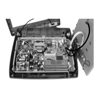
• Incorrect configuration jumper settings.
o The Workstation 5 supports a Capacitive Touchscreen, but as of
February 2009 this option has not entered production. If the
configuration jumpers are missing or set incorrectly, the symptoms may
appear as a calibration issue instead of a ‘no response to touch.’
message. Refer to Figure 3-9 to make sure the jumpers are set correctly.
Note that Pin 1 of the jumper block faces the IO Panel.