Workstation 5 Field Service Guide 4-15
Remove and Replace the Workstation 5 FRUs
LCD/Touchscreen Procedures
Backlight Inverter Board
The Backlight Inverter Board is attached to the LCD Plate with two screws.
1. Place the LCD/Touchscreen Assembly face down to access the Backlight
Inverter Board.
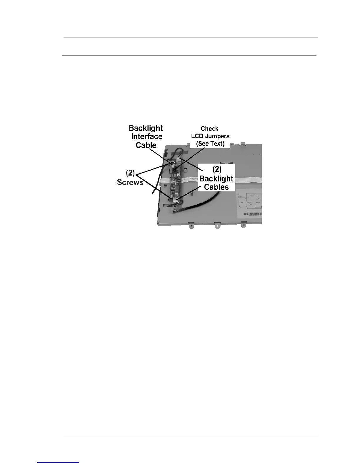
2. Refer to Figure 4-15 and remove the Backlight Cables. Remove the pair of
screws to remove the board.
Figure 4-15: Remove and Replace the Backlight Inverter Board
3. Remove the Backlight Interface Board Interface cable.
4. Examine the LCD Jumpers on both the defective Backlight Inverter Board,
and the Replacement Inverter Board. If necessary, change the LCD
Jumpers on the replacement board to match the original board.
5. Install the replacement board and fasten with two screws. Connect each
backlight cable and the system board interface cable to J1.
6. See page 4-27 to reinstall the LCD/Touchscreen Assembly.