Workstation 5 Field Service Guide 3-17
Workstation 5 Troubleshooting
Checking the Power Supply and System Board Voltages
WS5 System Board - Working Voltages
On a unit where the Standby voltages are present, but fails to respond to the
power button, the Working domain voltages can be checked as outlined in
Figure 3-5, below and the following text.
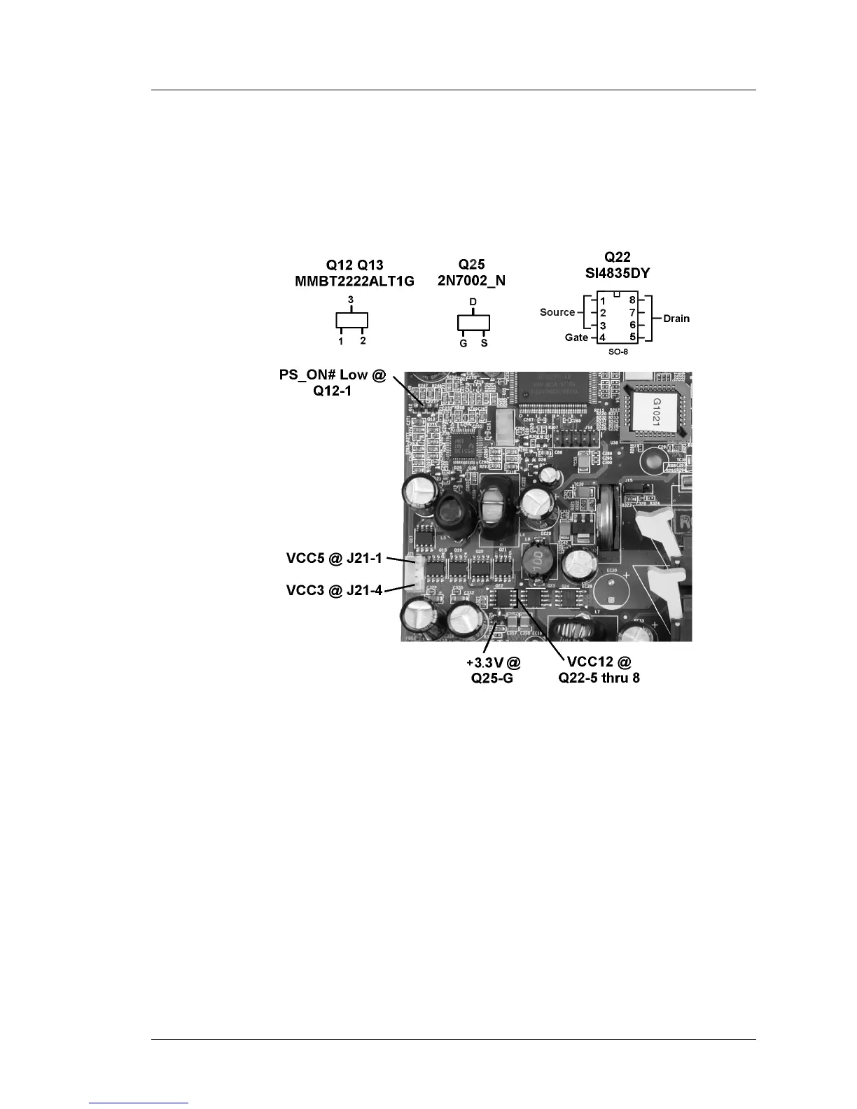
Figure 3-5: Checking the System Board Working Voltages
The working voltages depend on the standby voltages. Before proceeding,
make sure all standby voltages shown in Figure 3-4 are available.
With AC power connected, press the power button and check the following.
1. Start with PS_ON# at the base of Q12 or Q13. It should be low.
o Q12 and Q13 enable the VCC3 and VCC5 regulators, part of U38.
o PS_ON# is derived from the WORKING output of the Companion
Device. Q16 inverts WORKING to active-low PS_ON# (Sht. 8).
2. Check the VCC3 and VCC5 outputs at auxillary power connector J21. Pins 2
and 3 of J21 are ground. Watch those power supply heat sinks!
o VCC3 (3.3V) is available at Pin-1 (towards the IO connectors)