SECTION II
TESTING AND TROUBLESHOOTING
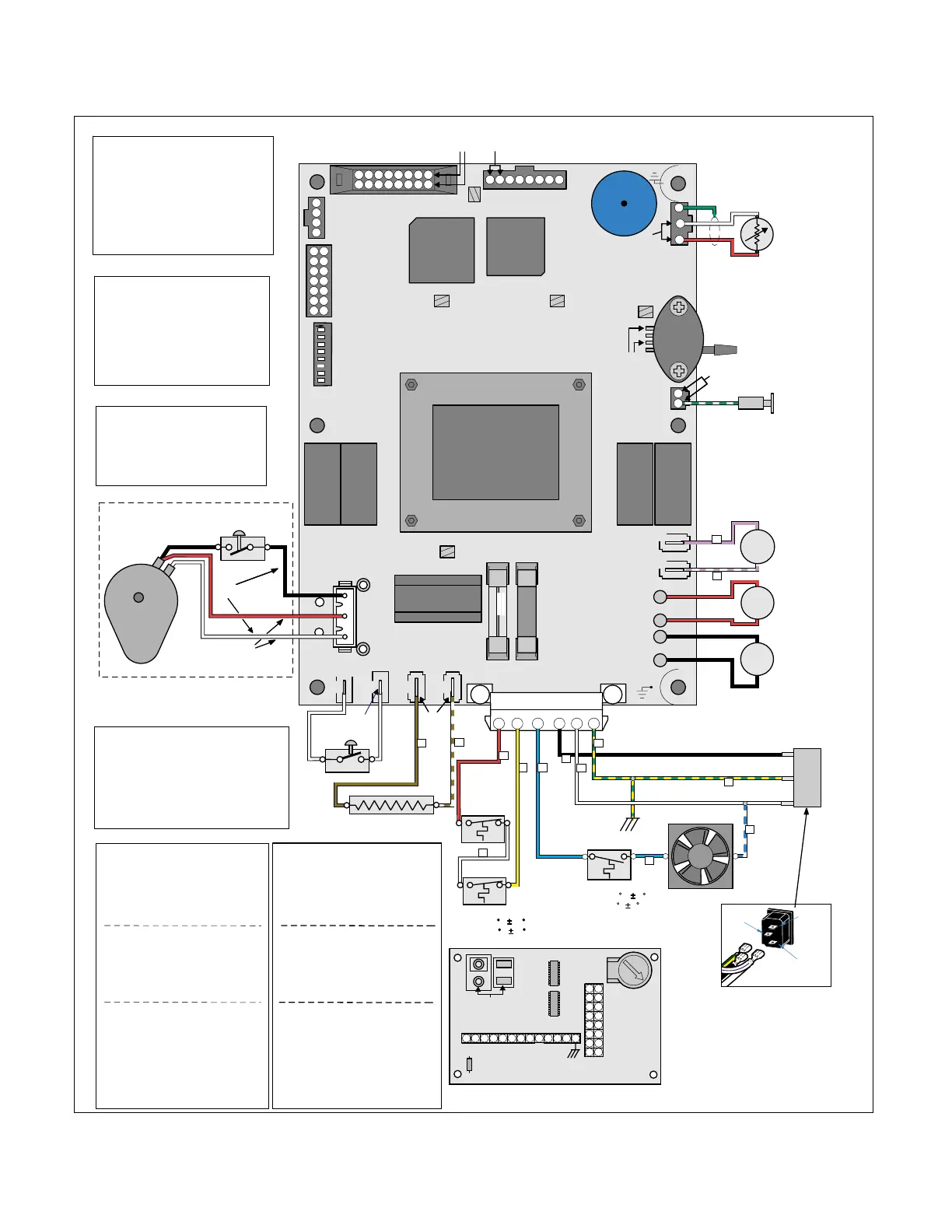
© Midmark Corporation 2002 SF-1803 Page 2-3 Printed in U.S.A.
White
Wht./Blue
Black
Grn/yl
Plug Outlet
MA612400
M9, M9D, M11, M11D
Sterilizer
Main P.C. Board
115 & 230 VAC
Single Phase 50 / 60 Hz
T1
Transformer
J1 J2 J3 J4
L1 N/L2
Heater
Door Interlock
Switch
W1
J5
F1
F2
W5
W6
W4
W3
J7
J6
Air
J8
Chamber
Level
U7
U8
SW1
(see Settings)
TP1
+12VDC*
TP2 Grd.
TP3
+5VDC*
TP4
+5VDC*
+5
VDC*
J12
Steam Temp
Sensor
DS1
TP5 Printer +5VDC*
J14 Printer
J13 Display
J10
RS232
PSD
JTAG
Port
J9
14
12
10
8
6
4
2
13
11
9
7
5
3
1
L1
High
Limit In
L1
VAC
Out
Fan
N / L2
L1
High
Limit
L1
(Line VAC)
Violet
Red
Blk
Wht
Grn/yl
Lt Blue
Grn
Fan Motor
Grn/yl
3
Lt
Blue
Lt
Blue
Blk
Yel
Fill
Vent
Fill
Solenoid
Coil (*)
Water
Level
Sensor
Probe
Wht/Blue
6
Wht
Vent (*)
Solenoid
Coil (NO)
Air
Solenoid
Coil (*)
Steam
Temperature
Sensor
Wht
Red
Red
Blk
Violet/Wht
Red
Blk
Wht / Grn
4
Brown
Brn/Wht
+5
VDC*
+4.5*
VDC
+4.5*
VDC
+5
VDC*
Line VAC
(When Door
is Open)
NO
C
Door
Interlock
Switch
Fan Thermostat (N/O)
Closes 130 F 8
Opens 101 F 6
C
NO
Pressure
Transducer
3
8
9
10
K4
Vent
Valve
K1
Heater
K5
Air
Valve
K2
Fill
Valve
4
5
6
11
12
7
1
4
3
2
1
135791113
15
2468101214
16
1234567
8
PS1
Line
VAC**
Wht
1
2
12
2
Wht
Grd.
Plug
Outlet
1
13
5
K3
Door
3
2
Red
Yel
Wht
Hi Limits (N/C)
Opens 450 F 25
Closes 350 F 25
14
J2
(To Switch Touch Pad)
D1
VR1
Display P.C. Board
R1
J3
(To J13 on Main
P.C. Board)
LCD Contrast
Adjustment
J1
16
3
1
5
7
9
11
13
15
2
4
6
8
10
12
14
+5VDC*
8765432
1
131211109
Line**
VAC
Line**
VAC
Line**
VAC
Steam Heating Element
Door
J15
3
C
NO
2
W2
1
Wht
Red
Blk
Blk
Door Opening
Motor Assy.
(M9 / Mll Only)
Switch
Motor
(Line Voltage
)
Line
VAC*
Line
VAC
NO
C
NC
C
(Motor Lever Arm
Depresses Switch
to open position)
(Energized for
12 secs. [1 1/2 rpm]
to 30 secs. [1 rpm] )
Wht
Red
SW1 Settings
Switch
1 On for Service Diagnostics
2 On for Model Designation
3, 4, 5 Not Used, leave Off
6 On for Communication Port
hook-up to computer.
7 Off-English, On-Metric
8 Not Used, Leave Off
4
3
2
1
8
7
6
5
ON
Test Points (TP)
TP2 - TP1 12 VDC supply to
K1 - K5 relay coils.
TP2 - TP3 5 VDC supply to
low voltage circuit
components.
TP2 - TP4 5 VDC supply to Temp.
& Pressure Sensors.
TP2 - TP5 5 VDC supply to Printer.
* Constant Voltage
** Voltage Present Only
During Component Operation
Note:
Disconnect plug connector
when checking voltage.
(*) NOTE:
Some Solenoid Coils may be
marked FWR (Full Wave Rectified)
Use the Mohms scale to measure
these coils. If reading is 0.2
Mohms or above, coil is GOOD.
If OL is displayed, coil is BAD.
115 VAC
Resistances (Ohms) Cold
(+ / - 10%)
Door Opening
Motor
(+/- 7.5%) 6000 - 9300 ohms
Fill Solenoid Note (*) M ohms
Air Solenoid Note (*) M ohms
Vent Solenoid Note (*) M ohms
Heating Element 10 Ohms
Electrical Requirements
104 to 127 VAC
50 / 60 Hz
Dedicated 15 Amp
Supply Circuit
Fuses
F1: 0.250 Amp, 250 V.
Slow Blow, 1/4"x1 1/4"
F2: 15 Amp, 250 V.
Fast Acting, 1/4"x1 1/4"
Electrical Requirements
207 to 250 VAC
50 / 60 Hz
Dedicated 15 Amp
Supply Circuit
230 VAC
Fuses
F1: 0.125 Amp, 250 V.
Slow Blow, 5 x 20mm
F2: 8 Amp, 250 V.
Fast Acting, 5 x 20mm
Resistances (Ohms) Cold
(+ / - 10%)
Door Opening
Motor
(+/- 7.5%) 13K - 16K ohms
Fill Solenoid Note (*) M ohms
Air Solenoid Note (*) M ohms
Vent Solenoid Note (*) M ohms
Heating Element 38 Ohms
Figure 2-2. Schematic
Rev. 9/25/03
Return To Table of Contents