SECTION II
TESTING AND TROUBLESHOOTING
© Midmark Corporation 2002 SF-1803 Page 2-21 Printed in U.S.A.
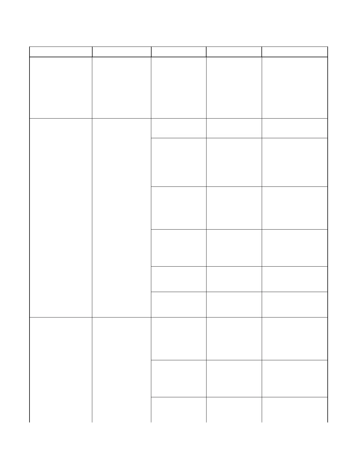
Code C677. (Continued)
(Error Type: FATAL )
(Continued)
C677: DRY MODE
PRESSURE OVERLIM
UNPLUG / RE-PLUG UNIT
Gauge pressure inside
chamber is greater than
34.8 PSIG (240 kPa) dur-
ing DRY mode.
Pressure Transducer or
Main P.C. Board Mal-
functioning.
Check for 5.0 VDC
between TP2 & TP4 &
pins of Pressure Trans-
ducer. (Refer to Sche-
matic in Section 5).
Voltage should be apprx.
4.5 VDC at all times with
unit plugged in. Also, run
Service Diagnostics.
If voltage is not present or Ser-
vice Diagnostics reveals a
problem replace P.C. Board
(Refer to para 4.13).
Code
C980.
(Error Type: FATAL )
Note: When a Code ends in
“0” it means unit had a sup-
ply power interruption.
The operator could have
unplug the unit when a previ-
ous Code was displayed.
Always go to Service Diag-
nostics and check previous 5
codes that are displayed.
C980: POWER UP MODE
HI-LIMIT OPEN
UNPLUG / RE-PLUG UNIT
High Limit Switch has
opened for at least 1/4 sec-
ond during POWER UP
mode.
May be due to a malfunc-
tion that occurred previ-
ously to displayed code.
Go to Service Diagnos-
tics and check previous 5
displayed codes.
Refer to Code Numbers in
Troubleshooting Guide to
determine correction.
Water level of reservoir is
covering outlet of con-
densing coil.
Water siphons back into
chamber resulting in low
temperature.
Check if condensing coil
outlet is beneath water
level in reservoir.
Inform operator not to over fill
reservoir.
If reservoir is not over filled but
coil outlet is submerged, bend
coil so outlet is a maximum of
1 7/8” below top of lid opening.
Do not allow coil to touch top
or sides of reservoir.
High Limit Switch(s) is
weak and opens prema-
turely.
Disconnect power and
check continuity across
high limit switches.
Limits opens at 425°F
(218°C) to 475°F (246°C)
Close at 325°F (163°C)
to 375° F (191° C)
If continuity is not present and
temperature at limit is below
the Limit’s “Open” temperature
replace Limit Switch (Refer to
para 4.19).
High Limit Switch(es)
opened normally due to
temperature surpassing
425°F (218°C) to 475°F
(246°C)
Disconnect power and
allow unit to cool. Run
Service Diagnostics and
check individual compo-
nents to assure they are
functioning correctly.
If a component malfunc-
tioned, producing the overheat
condition, repair or replace the
specific component.
Wires or connectors at
High Limit Switch(es)
loose, disconnected or
broken.
Check conditions of all
connectors and related
wires.
Repair or replace connectors
or wires. Refer to Section 5 for
Schematics.
P.C. Board malfunction-
ing.
Run Service Diagnostics
and make various volt-
age checks as indicated
on P.C. Schematic.
Replace P.C. Board (Refer to
para 4.13).
Code
C981 SELECT
Code C982 FILL
Code C983 HEATUP
Code C984 STERILIZE
Code C985 VENT
(Error Type: FATAL )
(Refer to column on left for
codes and description)
C98X: XXXXXX MODE
HI-LIMIT OPEN
UNPLUG / RE-PLUG UNIT
High Limit switch(es) has
opened for at least 1/4 sec-
ond during specific mode.
High Limit Switch(es) is
weak and opens prema-
turely.
Disconnect power and
check continuity across
high limit switch.
Limits opens at 425°F
(218°C) to 475°F (246°C)
Close at 325°F (163°C)
to 375° F (191° C)
If continuity is not present and
temperature at limit is below
the Limit’s “Open” temperature
replace Limit Switch (Refer to
para 4.19).
High Limit Switch(es)
opened normally due to
temperature surpassing
425°F (218°C) to 475°F
(246°C)
Disconnect power and
allow unit to cool. Run
Service Diagnostics and
check individual compo-
nents to assure they are
functioning correctly.
If a component malfunc-
tioned, producing the overheat
condition, repair or replace the
specific component.
Wires or connectors at
High Limit Switch(es)
loose, disconnected or
broken.
Check conditions of all
connectors and related
wires.
Repair or replace connectors
or wires. Refer to Section 5 for
Schematics.
Table 2-3. Troubleshooting Guide
Problem Display / Symptom Probable Cause Check Correction
Return To Table of Contents