SECTION IV
MAINTENANCE / SERVICE
© Midmark Corporation 2002 SF-1803 Page 4-1 Printed in U.S.A.
4.1 Safety Precautions
4.2 Top Cover & Panels.
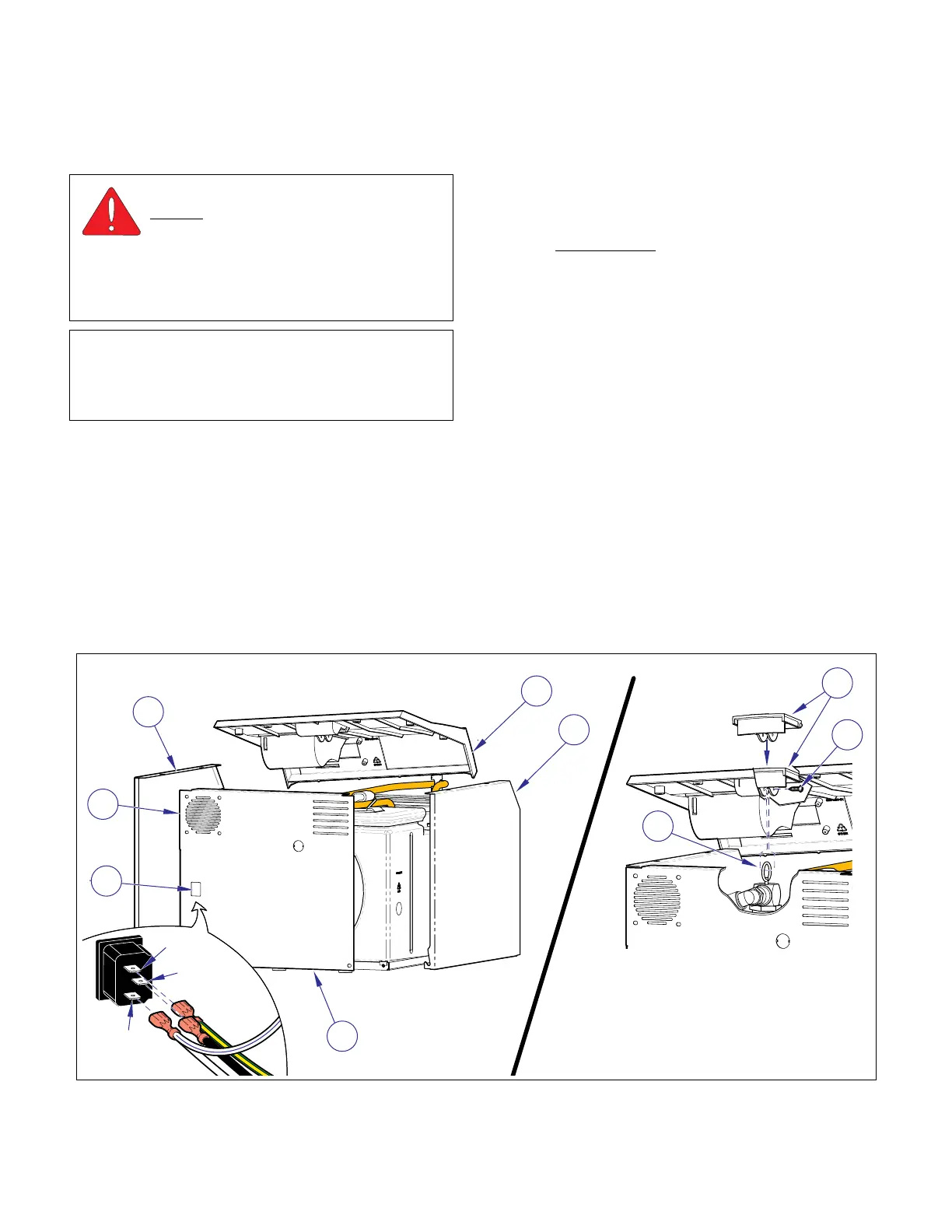
A. Removal
(1) Unplug unit power cord from electrical outlet.
(2) Remove screw (1, Figure 4-1) to separate pres-
sure relief valve (2) from handle (3).
(3) Remove right side panel (4), three screws.
(4) If unit is equipped with a printer remove it (Refer
to para. 4.23).
(5) Disconnect display cable from connector J3 on
Display board (Refer to para. 4.3).
(6) Remove the remaining screws from the top
cover (5) and remove the cover.
(7) Mark locations
then disconnect the electrical
leads from the receptacle (6) and fan motor (7)
on the back panel (8).
(8) Remove back (8) and left side panel (9).
B. Installation
(1) Place top cover (5, Fig. 4-1) in position.
(2) Connect pressure relief valve handle (3) to
pressure relief valve (2) with screw (1).
(3) Install left side (9) and back (8) panels securing
with screws.
(4) If unit is equipped with a printer install it (Refer
to para. 4.23).
(5) Connect display cable to connector J3 on Dis-
play board (Refer to para. 4.3).
(6) Connect the electrical leads to the receptacle
(6) and fan motor (7).
(7) Install the right side panel (4).
(8) Plug power cord into electrical receptacle.
WARNING
Always disconnect power cord from
outlet before removing any sterilizer
covers/panels or making any repairs to prevent
possibility of electrical shock. Allow unit to cool
and drain unit to prevent spillage during repairs.
Failure to comply could result in personal injury.
NOTE
Perform an operational test on sterilizer after the
repair is completed to confirm repair was properly
made and that all malfunctions were repaired.
Figure 4-1. Top Cover & Panels
4
5
9
8
6
7
1
2
3
MA617900i
Black
Grn/Yel
White
Wht/Blue
SECTION IV
MAINTENANCE / SERVICE INSTRUCTIONS
Return To Table of Contents