SECTION IV
MAINTENANCE / SERVICE
© Midmark Corporation 2002 SF-1803 Page 4-15 Printed in U.S.A.
4.23 Printer
A. Removal
(1) Unplug the sterilizer from the outlet.
(2) Remove the right side panel (refer to Para 4.2).
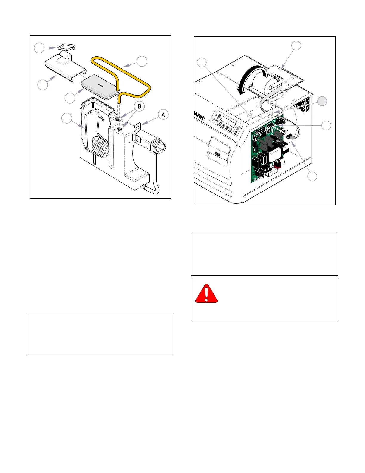
(3) Disconnect printer wire harness (1, Fig 4-27)
from the plug connector J14 on P.C. Board (2).
(4) Carefully lift printer assembly (3) from top cover
(4) while pulling the printer wire harness (1) out
thru the slot (A) of top cover.
(5) Slightly bend sides of printer assembly (3) out-
ward until printer housing (5) can be pulled off
locking tabs (B).
B. Installation
(1) Insert printer housing locking tabs (B, Figure
4-27) into slots of printer assembly (3).
(2) Route the printer wire harness (1) thru the slot
(A) of top cover (4).
(3) Connect the printer wire harness (1) to the plug
connector J8 on P.C. Board (2).
(4) Place printer in position on top cover (4).
(5) Install right side panel (refer to Para 4.2).
(6) Plug unit into outlet.
4.24 Pressure Gauge Test Harness.
A. Connecting Pressure Gauge
(1) Cut cable tie and disconnect the tube
(1, Figure 4-28) from pressure transducer (2).
(2) Connect tube of Pressure Gauge Test Harness
to pressure transducer (2).
(3) Connect tube (1) to fitting of Pressure Gauge
Test Harness.
B. Disconnecting Pressure Gauge Test Harness.
(1) Disconnect tube (1, Figure 4-28) from fitting of
Pressure Gauge Test Harness.
NOTE
Should it be necessary to install a new paper roll, car-
tridge ribbon, or perform maintenance on the printer,
refer to the M9 / M11 Sterilizer Installation / Operation
Manual.
MA616001i
3
4
5
1
2
Figure 4-26. Reservoir
NOTE
In order to check system pressure a Pressure Gauge
Harness is available (002-0372-00). The following
instructions pertain to connecting and disconnecting
the Pressure Gauge.
WARNING
Always assure power is disconnected
and there is no pressure in the system
before attempting to connect or disconnect the
Pressure Gauge.
R
1
3
A
MA595100i
4
2
Figure 4-27. Printer
Return To Table of Contents