SECTION IV
MAINTENANCE / SERVICE
© Midmark Corporation 2002 SF-1803 Page 4-10 Printed in U.S.A.
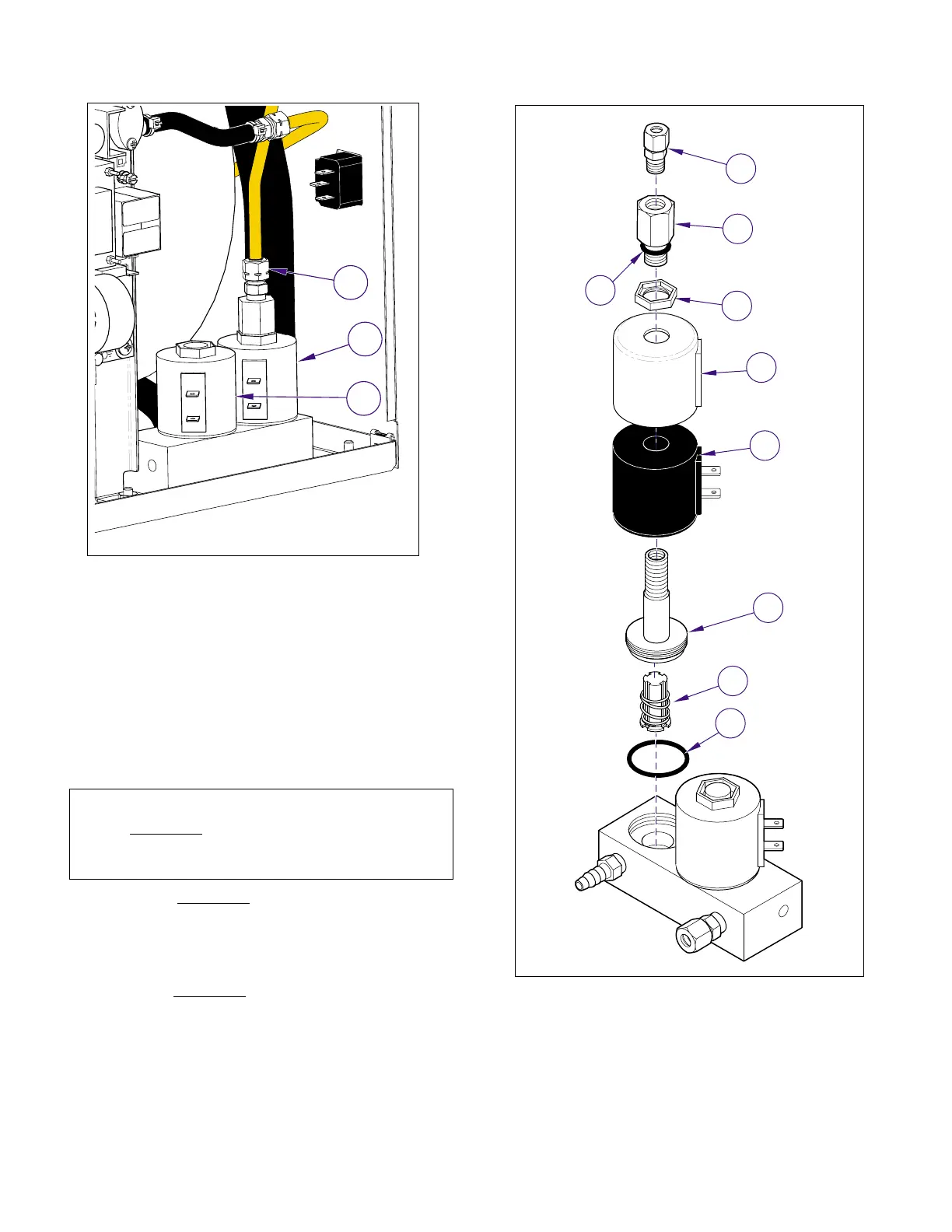
(3) Using a 3/4" spanner wrench, remove the
plunger housing (6), plunger (7) and o-ring
seal (8).
C. Assembly
(1) Position the new o-ring (8, Figure 4-19) in the
valve body, then install the new plunger (7) and
plunger housing (6).
(2) Install the solenoid coil (5), cover (4), and
nut (3).
(3) On the Vent Valve
, install the reducer (1) and
male connector (2) fittings.
D. Installation
(1) Connect the compression fitting (3, Figure 4.18)
on the Vent Valve
.
(2) Refill reservoir with distilled or demineralized
water (Refer to para 4.6).
(3) Plug unit in, run a cycle to place pressure on
lines and fittings; then check for leaks.
(4) Run Service Diagnostics to check operation of
Vent or Fill Solenoid Valve (2) (refer to Service
Diagnostics [Vent or Fill Valve Test], Para 2.2).
(5) Install panels (Refer to para 4.2).
NOTE
On the Vent Valve, replace the o-ring (9) located on
the end of the reducer (1) before installing on plunger
housing (6).
Figure 4-18. Vent / Fill Valves
MA619800i
1
2
3
Figure 4-19. Vent / Fill Valves
5
4
6
7
8
MA619900i
FILL
VENT
9
3
1
2
Return To Table of Contents