SECTION IV
MAINTENANCE / SERVICE
© Midmark Corporation 2002 SF-1803 Page 4-13 Printed in U.S.A.
4.21 Water Level Sensor
A. Removal
(1) Unplug the sterilizer from the outlet.
(2) Remove the right side and back panels (refer to
Para 4.2).
(3) Open the door and remove the trays and tray
rack (refer to para 4.5).
(4) Disconnect the red lead (1, Figure 4-23) from
the water level sensor.
(5) Remove the nut (2) and terminal (3).
(6) Remove the compression nut (4).
(7) Push the level sensor (5) thru the chamber wall
to the inside of the chamber and remove the
sensor and spacer (6).
B. Installation
(1) Install the teflon tube (7, Figure 4-23) and
spacer (6) on the level sensor (5) and, insert
from inside chamber, thru the chamber wall.
(2) Install compression nut (4). Do
not over-
tighten. Tighten 1 1/4 turns from finger tight and
then install terminal (3) and nut (2).
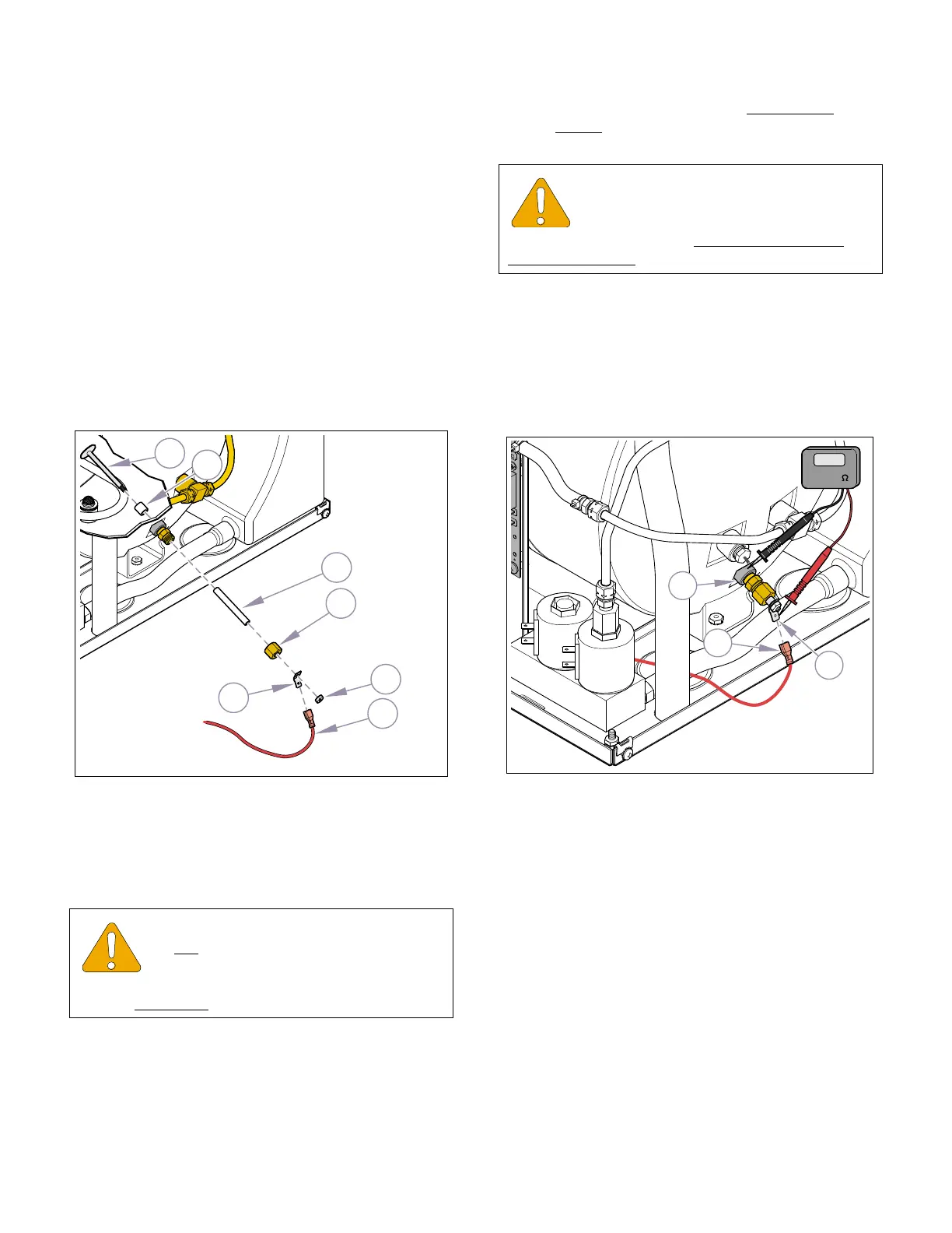
(3) Check to assure the sensor is not grounded
against the chamber using an ohmmeter.
Place one probe on the sensor terminal
(1, Figure 4-24) and the other on the chamber
wall (2). No reading should be present.
(4) Connect the electrical lead (3) to the sensor ter-
minal (4).
(5) Run Service Diagnostics to check operation
and for leaks (refer to Service Diagnostics, Para
2.2).
(6) Install panels (refer to Para 4.2).
4.22 Reservoir
A. Removal
(1) Unplug the sterilizer from the outlet.
(2) Drain the reservoir (refer to Para 4.6).
(3) Remove the top cover and panels (refer to
para. 4.2).
(4) Disconnect the tubing (1,Figure 4-25 ) at top of
reservoir (2) that goes to the Air Valve .
(5) Disconnect tubing (3) at bottom of reservoir that
goes to the Fill Valve.
EQUIPMENT ALERT
Do not over-tighten compression fitting or
the ferrule could cut through the teflon
sleeve resulting in the sensor shorting out.
Tighten 1 1/4 turns
from finger tight.
Figure 4-23. Water Level Sensor
MA617401i
1
2
3
4
7
6
5
EQUIPMENT ALERT
Before installing electrical leads, use an
ohmmeter and check to assure sensor is
not grounded to chamber. No continuity reading
should be present.
MA617500i
1
2
3
OL
200
(ohms)
Figure 4-24. Water Level Sensor
Return To Table of Contents