SECTION IV
MAINTENANCE / SERVICE
© Midmark Corporation 2002 SF-1803 Page 4-2 Printed in U.S.A.
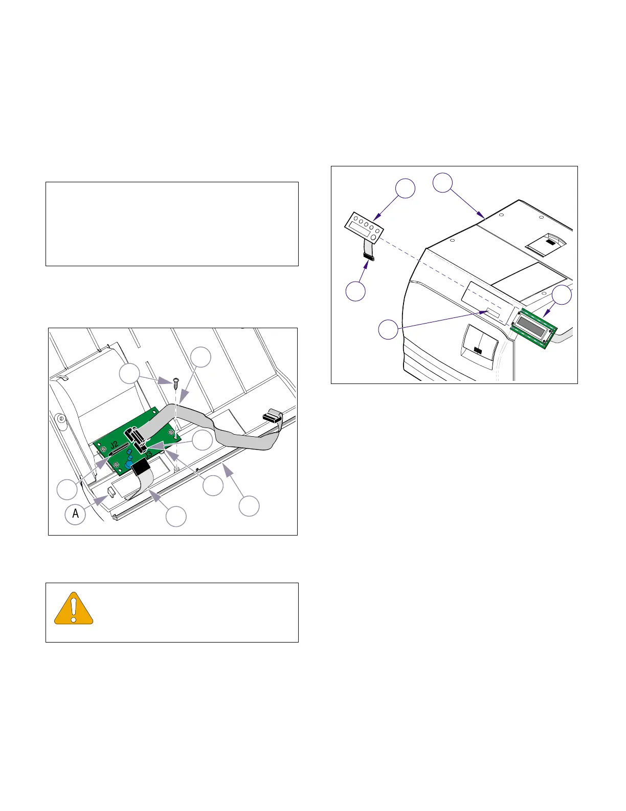
4.3 Display P.C. Board
A. Removal
(1) Unplug power cord from electrical outlet.
(2) Remove top cover (Refer to para 4.2).
(3) Disconnect display harness (1, Fig. 4-2) from
connector J3 (2) of display PCB (3).
(4) Disconnect touchpad harness (4) from connec-
tor J2 (5) of display PCB (3)
(5) Remove the two screws (6) and while carefully
separating the Display PCB (3) from the Decal
Switch, slide the Display PCB free from under
the tab (A).
B. Installation
(1) Install display PCB (3, Figure 4-2) on top cover
(7) securing with two screws.
(2) Connect touchpad harness (4) to connector
J2 (5)
(3) Connect PCB harness (1) to connector J3 (2).
(4) Install top cover (Refer to para 4.2).
(5) Plug unit power cord into electrical outlet.
4.4 Decal Switch
A. Removal
(1) Unplug power cord from electrical outlet.
(2) Remove top cover (Refer to para 4.2).
(3) Disconnect ribbon harness (1, Figure 4-3) from
display PCB (2).
(4) Using a sharp instrument, carefully remove
decal switch (3) from front of top cover (4).
(5) Use an all citrus solvent / degreaser that does
not harm plastics to remove all adhesive resi-
due and then allow top cover to dry.
B. Installation
(1) Peel protective backing from back side of new
decal switch (3, Figure 4-3).
(2) Install new decal switch (3) on top cover (4),
making sure ribbon harness (1) is fed thru wire
slot (A).
(3) Connect ribbon harness (1) to connector on dis-
play PCB (2).
(4) Install top cover (Refer to para 4.2).
(5) Plug power cord into electrical outlet.
NOTE
The Display PCB (3) may be stuck to the adhesive
backing of the Decal Switch. Use care to prevent
damage when separating the components. A plastic
tab on the cover secures the one end of the Display
PCB.
EQUIPMENT ALERT
Assure display PCB is positioned correctly
when installing. An arrow indicating cor-
rect direction for UP is on front of PCB.
Figure 4-2. Display PCB
MA615901i
1
3
6
7
4
5
2
Figure 4-3 Decal Switch
MA616100
1
3
2
A
4
Return To Table of Contents