SECTION IV
MAINTENANCE / SERVICE
© Midmark Corporation 2002 SF-1803 Page 4-12 Printed in U.S.A.
4.20 Heating Element
A. Removal
(1) Unplug Sterilizer from outlet.
(2) Remove trays and tray rack (refer to para 4.5).
(3) Remove R.H. and back panel (refer to
para 4.2).
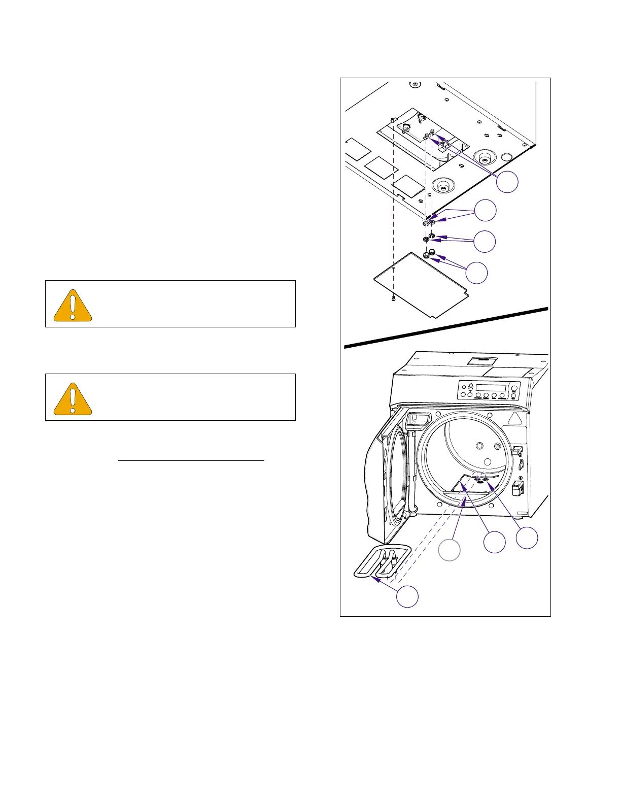
(4) Disconnect leads from terminals of heating ele-
ment (1, Figure 4-21).
(5) Remove nuts (2), lockwashers (3), and brass
washer (4).
(6) Disengage heating element (1) from hook
bracket (A) inside chamber and remove heating
element (1) and spacer (5).
B. Installation
(1) Install heater gaskets (6, Figure 4-22) on ends
of heating element (2) and install spacer (5) and
heating element (1) in chamber.
(2) Install brass washers (4), lockwashers (3), and
nuts (2) on ends of heating element (2) and
tighten. Do not exceed maximum torque.
(3) Connect electrical leads (1).
(4) Install tray rack and trays (refer to Para 4.5).
(5) Run Service Diagnostics to check operation
and for leaks (refer to Service Diagnostics, Para
2.2).
(6) Install panels (Refer to para. 4.2).
(7) Plug unit into electrical outlet.
EQUIPMENT ALERT
Spacer must be in position beneath heat-
ing element.
EQUIPMENT ALERT
The torque applied to heating element nuts
should not exceed 25 ft./lbs. ( 34 N•M ).
2
3
1
4
MA618100i
A
6
5
1
Figure 4-21. Heating Element
Return To Table of Contents