SECTION IV
MAINTENANCE / SERVICE
© Midmark Corporation 2002 SF-1803 Page 4-5 Printed in U.S.A.
B. Installation
(1) Install axial flow fan (2, Figure 4-9) assuring
flow arrow is point inward
, and secure with four
screws.
(2) Connect two wires (1)
(3) Install right side panel (Refer to para 4.2).
(4) Plug power cord into outlet receptacle.
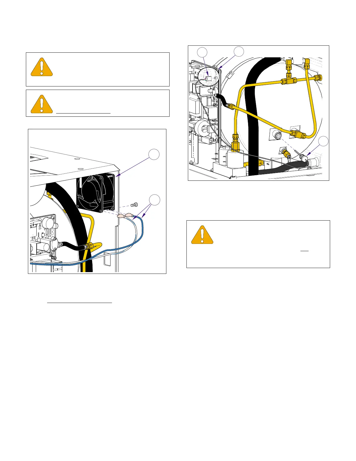
4.10 Steam Temperature Sensor
A. Removal
(1) Unplug power cord.
(2) Remove right side and back panels (Refer to
para 4.2).
(3) Disconnect temperature probe harness
(1, Figure 4-10) from connector J12 on main
p.c. board (2).
(4) Remove temperature probe assembly (3) from
fitting.
B. Installation
(1) Coat threads of temperature probe assembly
(3, Figure 4-10) with high temperature pipe
thread compound (Loctite 565).
(2) Install temperature probe assembly (3).
(3) Connect temperature probe harness (1) to con-
nector J12 on main p.c. board (2) .
(4) Run a cycle, to place pressure on fittings, then
check for leaks.
(5) Install panels (Refer to para 4.2).
(6) Plug power cord into outlet receptacle.
EQUIPMENT ALERT
Check fan intake openings; make sure
intake is clear of any debris that would
restrict air flow.
EQUIPMENT ALERT
Flow arrow on fan body must be pointed
toward
inside of case when installing fan.
MA616600i
2
1
Figure 4-9. Axial Flow Fan
EQUIPMENT ALERT
Use a pipe thread compound on the steril-
izer fittings capable of withstanding the
operating pressures and temperatures. Do not
use a
teflon tape as particles may migrate through system
and cause blockage.
J12
1
2
3
MA616700i
Figure 4-10. Steam Temperature Probe
Return To Table of Contents