SECTION IV
MAINTENANCE / SERVICE
© Midmark Corporation 2002 SF-1803 Page 4-9 Printed in U.S.A.
(7) If excessive force is required to open pressure
relief valve or pressure relief valve will not
reseat properly, the pressure relief valve must
be replaced (Refer to para. 4.17).
4.17 Pressure Relief Valve
A. Removal
(1) Unplug power cord from outlet receptacle.
(2) Remove all panels and top cover (Refer to
para 4.2).
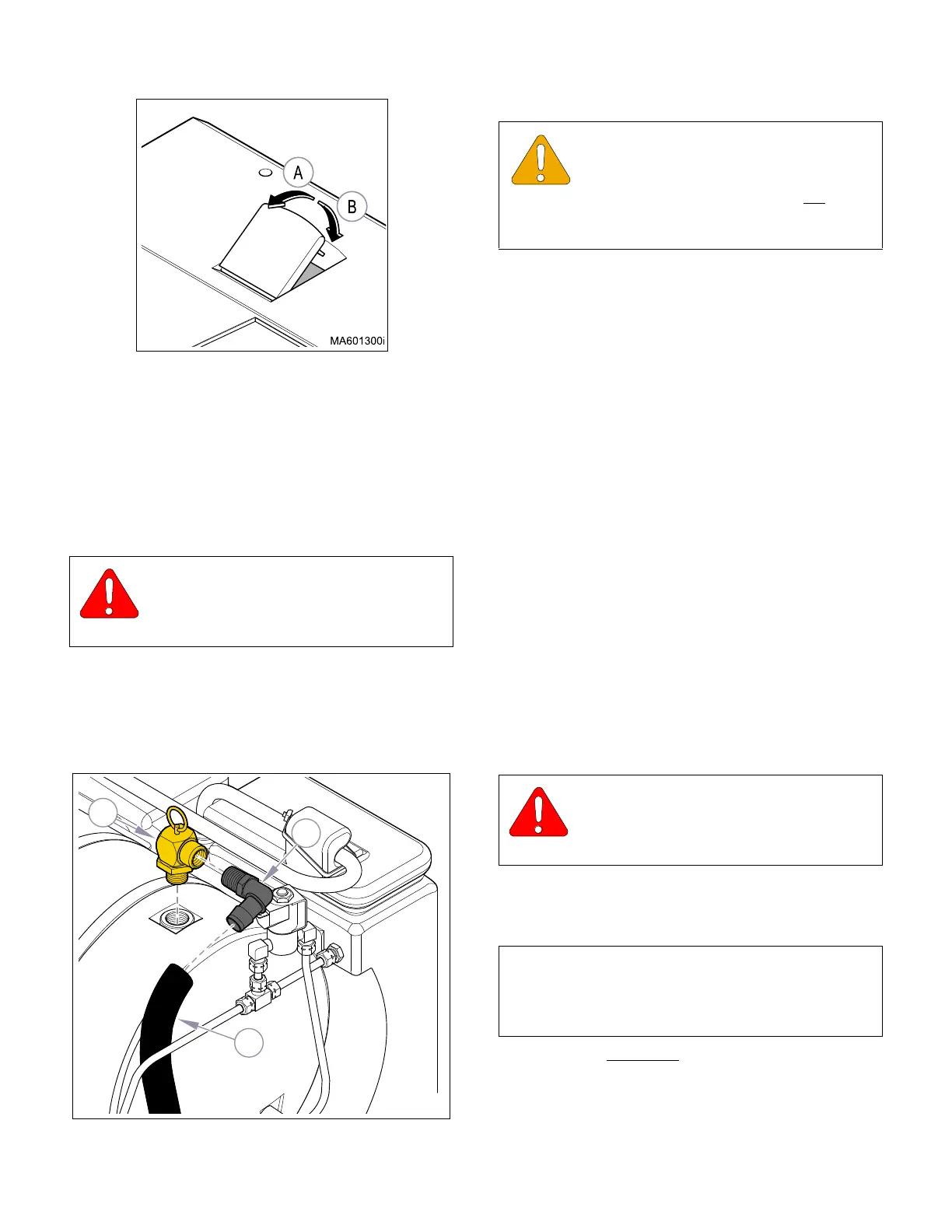
(3) Remove tubing (1, Figure 4-17) and elbow (2)
from pressure relief valve (3).
(4) Remove pressure relief valve (3).
B. Installation
(1) Coat threads of pressure relief valve
(3, Figure 4-26) with high temperature
pipe thread compound (Loctite 565).
(2) Install pressure relief valve (3).
(3) Install elbow (2) on pressure relief valve (3).
(4) Install tubing (1) on elbow (2) and route tubing
through tubing hole in bottom, back of base.
(5) Install L.H. panel and Top Cover (Refer to
para. 4.2).
(6) Plug unit in, run a cycle to place pressure on
lines and fittings, then check for leaks and oper-
ation of pressure relief valve (3).
(7) Install Back and R.H. side panel (Refer to
para 4.2).
4.18 Vent or Fill Valve
A. Removal
(1) Unplug power cord from outlet receptacle.
(2) Remove R.H. side and back panel (Refer to
para 4.2).
(3) Drain water from reservoir (Refer to para 4.6).
(4) Disconnect electrical wires from terminals of
the Vent (1, Figure 4-18) or Fill (2) solenoid
valve.
(5) If removing Vent Valve (1) , disconnect com-
pression fitting (3) and line on top of valve.
B. Disassembly
(1) On the Vent Valve
, remove the reducer
(1, Figure 4-19) and male connector (2) fittings.
(2) Remove nut (3), solenoid cover (4), and sole-
noid coil (5).
WARNING
Pull upward on the pressure relief handle
to purge any pressure inside chamber
(Refer to para 4.16).
Figure 4-16. Pressure Relief
Figure 4-17. Pressure Relief Valve
MA617600i
1
3
2
EQUIPMENT ALERT
Use a pipe thread compound on the steril-
izer fittings capable of withstanding the
operating pressures and temperatures. Do not
use a
teflon tape as particles may migrate through system
and cause blockage.
WARNING
Pull up on Pressure Relief Valve handle
to purge any pressure inside chamber
and lines before working on system.
NOTE
The steps for disassembly and assembly of the Vent
or Fill Valves are almost identical unless called out for
the specific valve.
Return To Table of Contents