SECTION IV
MAINTENANCE / SERVICE
© Midmark Corporation 2002 SF-1803 Page 4-14 Printed in U.S.A.
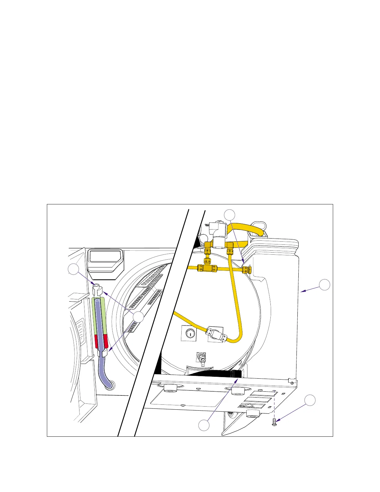
(6) Pull the level indicator / drain tube (4) loose
from the hose clips (5).
(7) Remove the two mounting bolts (6) and remove
the reservoir (2).
B. Disassembly
(1) Cut the cable tie (1, Figure 4-26) and remove
the equalization tube (2).
(2) Slide off the reservoir lid (3) and remove the
tank seal (4)
(3) Disconnect condensing coil (5) and remove it.
C. Assembly
(1) Place condensing coil (5, Figure 4-26) in posi-
tion and connect fittings.
(2) Install the tank seal (4) and slide on the reser-
voir lid (3).
(3) Place the equalization tube (2) in position on
the bracket (A) and insert ends into grommets
(B) in top of reservoir.
(4) Install the cable tie (1).
D. Installation
(1) Place the reservoir (2, Figure 4-25) in position
and secure to base with two screws (6).
(2) Connect the Fill Valve tubing (3), and Air Valve
tubing (1) to the reservoir (2).
(3) Position the level indicator / drain tube (4) into
the hose clips (5).
(4) Pour distilled water in the reservoir.
(5) Install the back panel (Refer to para. 4.2).
(6) Plug unit into electrical outlet, run a cycle, and
check for leaks.
(7) Install remaining panels (Refer to para 4.2).
2
MA615600i
1
4
5
3
6
Front View
Back View
Figure 4-25. Reservoir
Return To Table of Contents