SECTION V
SCHEMATICS AND DIAGRAMS
© Midmark Corporation 2002 SF-1803 Page 5-3 Printed in U.S.A.
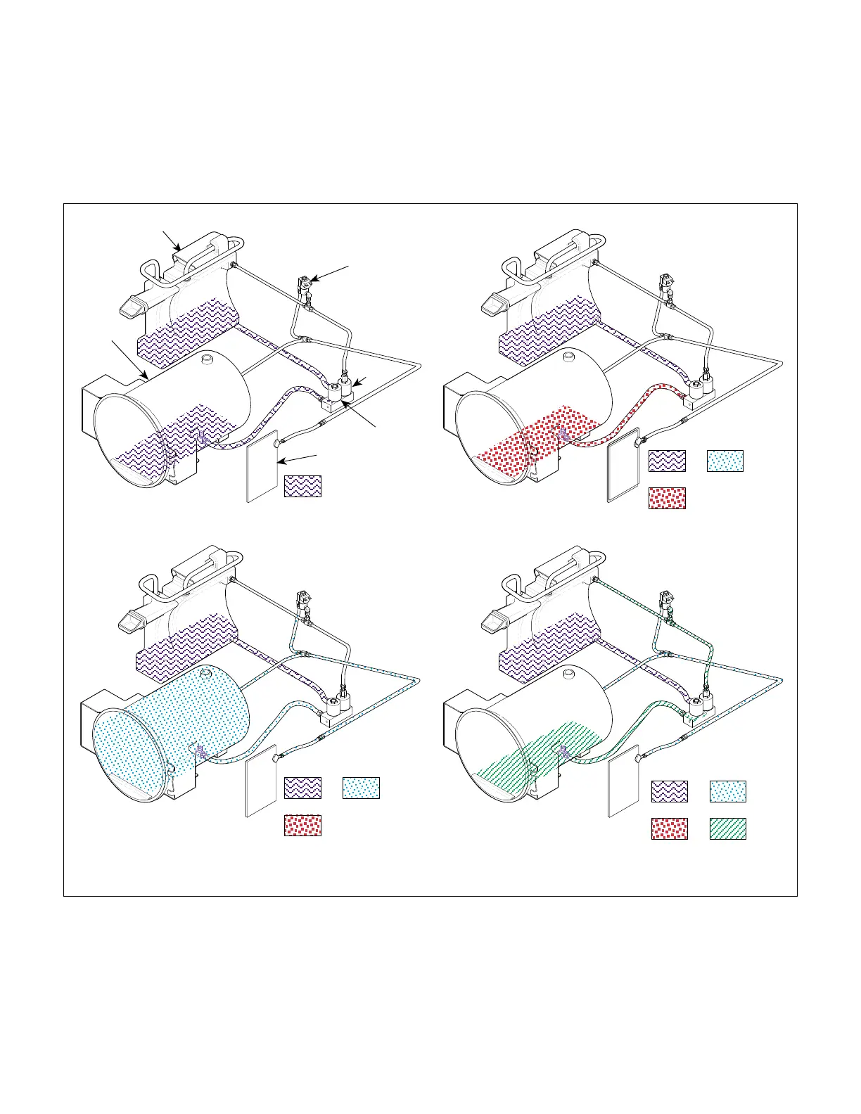
5.2 Flow Diagram
The Flow Diagram illustrates the water, heated water,
steam, and vented steam / water flow through the Steril-
izer during the Fill, Heat-Up, Sterilizing, and Vent Modes
during a complete operation.
Water
Heated
Water
Steam
Vented
Steam/Water
PHASE 1 (Filling)
PHASE 2 (Heat-Up)
PHASE 3 (Sterilizing)
PHASE 4 (Vent)
Steam/Air
Condensing
Tank / Reservoir
Pressure
Vessel
Control
PC
Board
Air
Soleniod
Fill
Solenoid
Vent
Solenoid
MA618600
Water
Heated
Water
Steam/Air
Steam/AirWater
Heated
Water
Steam/Air
Water
Return To Table of Contents