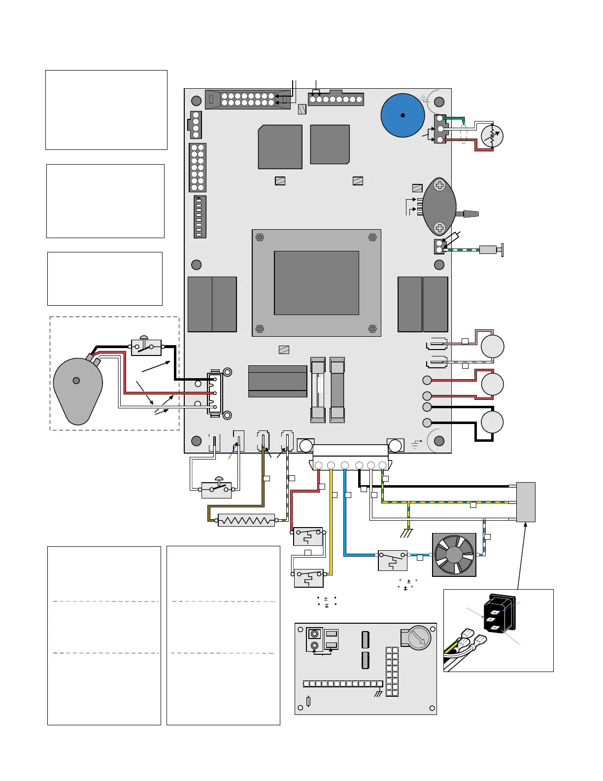
SECTION V
SCHEMATICS AND DIAGRAMS
© Midmark Corporation 2002 SF-1803 Page 5-2 Printed in U.S.A.
White
Wht./Blue
Black
Grn/yl
Plug Outlet
MA612400
M9, M9D, M11, M11D
Sterilizer
Main P.C. Board
115 & 230 VAC
Single Phase 50 / 60 Hz
T1
Transformer
J1 J2 J3 J4
L1 N/L2
Heater
Door Interlock
Switch
W1
J5
F1
F2
W5
W6
W4
W3
J7
J6
Air
J8
Chamber
Level
U7
U8
SW1
(see Settings)
TP1
+12VDC*
TP2 Grd.
TP3
+5VDC*
TP4
+5VDC*
+5
VDC*
J12
Steam Temp
Sensor
DS1
TP5 Printer +5VDC*
J14 Printer
J13 Display
J10
RS232
PSD
JTAG
Port
J9
14
12
10
8
6
4
2
13
11
9
7
5
3
1
L1
High
Limit In
L1
VAC
Out
Fan
N / L2
L1
High
Limit
L1
(Line VAC)
Violet
Red
Blk
Wht
Grn/yl
Lt Blue
Grn
Fan Motor
Grn/yl
3
Lt
Blue
Lt
Blue
Blk
Yel
Fill
Vent
Fill
Solenoid
Coil
Water
Level
Sensor
Probe
Wht/Blue
6
Wht
Vent
Solenoid
Coil (NO)
Air
Solenoid
Coil
Steam
Temperature
Sensor
Wht
Red
Red
Blk
Violet/Wht
Red
Blk
Wht / Grn
4
Brown
Brn/Wht
+5
VDC*
+4.5*
VDC
+4.5*
VDC
+5
VDC*
Line VAC
(When Door
is Open)
NO
C
Door
Interlock
Switch
Fan Thermostat (N/O)
Closes 130 F 8
Opens 101 F 6
C
NO
Pressure
Transducer
3
8
9
10
K4
Vent
Valve
K1
Heater
K5
Air
Valve
K2
Fill
Valve
4
5
6
11
12
7
1
4
3
2
1
135791113
15
2468101214
16
1234567
8
PS1
Line
VAC**
Wht
1
2
12
2
Wht
Grd.
Plug
Outlet
1
13
5
K3
Door
3
2
Red
Yel
Wht
Hi Limits (N/C)
Opens 450 F 25
Closes 350 F 25
14
J2
(To Switch Touch Pad)
D1
VR1
Display P.C. Board
R1
J3
(To J13 on Main
P.C. Board)
LCD Contrast
Adjustment
J1
16
3
1
5
7
9
11
13
15
2
4
6
8
10
12
14
+5VDC*
8765432
1
131211109
Line**
VAC
Line**
VAC
Line**
VAC
Steam Heating Element
Door
J15
3
C
NO
2
W2
1
Wht
Red
Blk
Blk
Door Opening
Motor Assy.
(M9 / Mll Only)
Switch
Motor
(Line Voltage
)
Line
VAC*
Line
VAC
NO
C
NC
C
(Motor Lever Arm
Depresses Switch
to open position)
(Energized for
apprx. 12 secs.)
Wht
Red
SW1 Settings
Switch
1 On for Service Diagnostics
2 On for Model Designation
3, 4, 5 Not Used, leave Off
6 On for Communication Port
hook-up to computer.
7 Off-English, On-Metric
8 Not Used, Leave Off
4
3
2
1
8
7
6
5
ON
Test Points (TP)
TP2 - TP1 12 VDC supply to
K1 - K5 relay coils.
TP2 - TP3 5 VDC supply to
low voltage circuit
components.
TP2 - TP4 5 VDC supply to Temp.
& Pressure Sensors.
TP2 - TP5 5 VDC supply to Printer.
* Constant Voltage
** Voltage Present Only
During Component Operation
Note:
Disconnect plug connector
when checking voltage.
Electrical Requirements
207 to 250 VAC
50 / 60 Hz
Dedicated 15 Amp
Supply Circuit
230 VAC
Fuses
F1: 0.125 Amp, 250 V.
Slow Blow, 5 x 20mm
F2: 8 Amp, 250 V.
Fast Acting, 5 x 20mm
Resistances (Ohms) Cold
(+ / - 10%)
Door Opening
Motor
(+/- 7.5%)
14,900 Ohms
Fill Solenoid 3.6 M ohms
Air Solenoid 3.5 M ohms
Vent Solenoid 3.2 M ohms
Heating Element 38 Ohms
115 VAC
Fuses
F1: 0.250 Amp, 250 V.
Slow Blow, 1/4"x1 1/4"
F2: 15 Amp, 250 V.
Fast Acting, 1/4"x1 1/4"
Resistances (Ohms) Cold
(+ / - 10%)
Door Opening
Motor
(+/- 7.5%)
9316 Ohms
Fill Solenoid 0.4 M ohms
Air Solenoid 0.4 M ohms
Vent Solenoid 0.4 M ohms
Heating Element 10 Ohms
Electrical Requirements
104 to 127 VAC
50 / 60 Hz
Dedicated 15 Amp
Supply Circuit
Return To Table of Contents