SECTION V
SCHEMATICS AND DIAGRAMS
© Midmark Corporation 2002 SF-1803 Page 5-1 Printed in U.S.A.
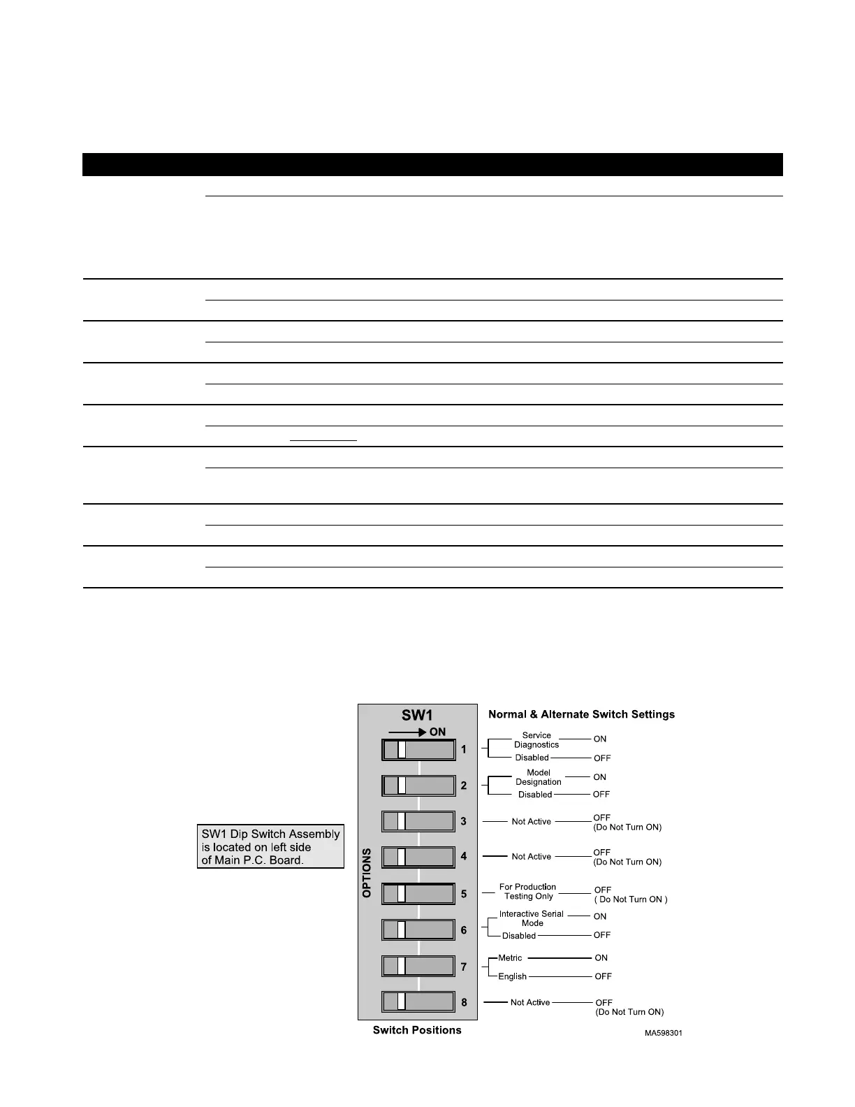
5.1 SW1 Dip Switch Settings.
Switch Position Result
#1
OFF Disabled
ON Service Diagnostics
Allows Technician to:
a.) Turn ON / OFF all Outputs.
b.) Verify Keypad functions.
c.) Monitor Steam and Auxiliary Temperature readings.
#2 OFF Disabled
ON Enter Model Designation (M9, M11, M9D, M11D) to Configure Software.
#3 OFF Not Active (Do not turn ON) No effect on software.
ON
#4 OFF Not Active (Do not turn ON) No effect on software.
ON
#5 OFF Disabled
ON Do Not Use
. Factory Test Mode. Unusable in Field
#6 OFF Disabled
ON Interactive Serial Mode (Allows communciation thru a RS-232 interface
connection to P.C. Board).
#7 OFF Displays English (Temperature in °F, Pressure in PSI)
ON Displays Metric (Temperature in °C, Pressure in kPa)
#8 OFF Not Active (Do not turn ON) No effect on software.
ON
NOTE:
For Switches # 1 thru # 6:
LOWER numbered switches take precedence over HIGHER numbered when BOTH switches are ON.
Example: If both Switch # 1 (Diagnostics) & Switch # 4 Atmospheric Pressure Entry were ON,
Switch # 1 would take priority over # 4.
SECTION V
SCHEMATICS AND DIAGRAMS
Return To Table of Contents