SECTION IV
MAINTENANCE / SERVICE
© Midmark Corporation 2002 SF-1803 Page 4-11 Printed in U.S.A.
4.19 Hi-Limit Thermostats
A. Removal
(1) Unplug power cord from outlet receptacle.
(2) Drain water from reservoir (Refer to para 4.6).
(3) Remove R.H. side panel (Refer to para 4.2).
(4) Remove trays and tray rack (Refer to para 4.5).
(5) Lay sterilizer over onto its left side.
(6) Remove base inspection cover (1, Figure 4-20).
(7) First tag, then disconnect the wires from the two
hi-limit thermostats (2) and heating element (3).
(8) Remove the nuts (4), lockwashers (5), and
brass washers (6) from the heating element.
(9) Remove the thermostat bracket (7) and hi-limit
thermostats (2).
B. Installation
(1) Place the thermostat bracket (7, Figure 4-19)
and hi-limit thermostats (2) in position.
(2) Install the brass washers (6), lockwashers (5),
and nuts (4) on the heating element (3).
(3) Connect the white
jumper wire (1, Figure 4-20)
between the two high limit thermostats (2).
(4) Connect the yellow
lead (3) to one of the ther-
mostats and the red
lead (4) to the other.
(5) Connect the brown
(5) and brown and white (6)
leads to the terminals (7) of the heating ele-
ment.
(6) Install base inspection cover (1, Figure 4-19)
and set unit upright.
(7) Install trays and tray rack (Refer to para 4.5).
(8) Refill reservoir with distilled water (Refer to
para 4.6).
(9) Run Service Diagnostics to check operation
(refer to Service Diagnostics, Para 2.2).
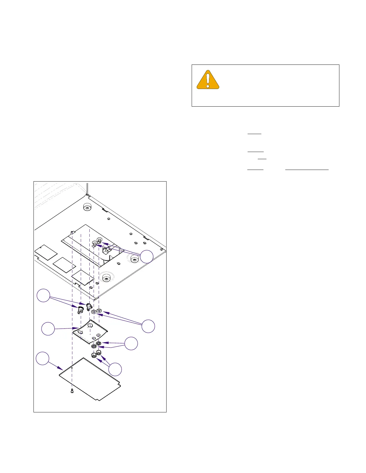
Figure 4-20. High Limit Thermostats
MA618000i
2
3
4
5
7
6
1
EQUIPMENT ALERT
Before tightening the nuts that secure the
heating element assure the wire spacer is
in position beneath the heating element and the gas-
kets not damaged (Refer to para 4.20).
Return To Table of Contents