SECTION I
GENERAL INFORMATION
© Midmark Corporation 2002 SF-1803 Page 1- 2 Printed in U.S.A.
Air Valve
A Normally Closed
Valve that, when energized open,
removes air from chamber expelling it into the reservoir
thru the condensing coil during operation. Controlled by
main control p.c. board. Valve is located on top, back of
pressure vessel.
Temperature Probe
Temperature probe monitors internal chamber tempera-
ture during operation and transmits it back to main p.c.
board. The probe is located in the back of the chamber.
Main Control P.C. Board
Contains the program logic, and various connections to
send and receive data to operate the various programs.
SW1 dip switch assembly is located on the left side of
the board. Service Diagnostics, and various display
options can be accessed by changing switch positions.
Fuses F1 and F2 protect the main control p.c. board.
Hi-Limit Switches
Controls power to heating elements and various compo-
nents should overheat conditions exist.
Two normally closed, bimetal, thermostats that automat-
ically opens contacts at 425°F (218°C) to 475°F (246°C)
removing power to heating elements.
They automatically reset to the closed position at 325°F
(163°C) to 375°F (191°C).
They are located on lower
, outside surface of chamber.
Water Level Sensor
Located in back of chamber, it monitors the water level
during the FILL cycle. When the water level reaches the
sensor, a circuit is completed which signals the main
control P.C. board to remove power from the Fill Valve
solenoid, closing the valve.
Fill Valve
Fill Valve is a Normally Closed
valve. The Door Interlock
switch must be closed to operate the Fill Valve. When
the START key is depressed the Fill Valve solenoid is
energized. The valve opens
, allowing water to enter the
chamber. When water reaches the Water Level Sensor
a circuit is completed, removing power from the Fill
Valve solenoid coil, closing the valve.
Vent Valve
Vent Valve is a Normally Open
valve controlled by the
main control P.C. board. When K4 contacts on the Main
P.C. Board close, the solenoid of the Vent Valve ener-
gizes, closing
the valve. In the open position, the valve
vents back thru the condensing coil in the reservoir.
Display / P.C. Board
Operation and Service Diagnostic messages are
viewed though use of a liquid crystal display (LCD) on
the front of the top cover.
Heating Element
Submersible, tubular, 1425 watt (115 VAC) or 1500 watt
(230 VAC), heating element used to generate steam for
the sterilizer.
During the Heatup, Sterilization and Dry cycles the tem-
perature probe monitors internal chamber conditions,
sending signals back to main control P.C. board which
controls On / Off cycling of heater.
Pressure Relief Valve
The ASME approved Safety valve opens to vent the
chamber should pressure inside chamber reach 40
PSIG [+/-2 PSI] (275.8 kPa). The steam is vented out
below base of sterilizer.
Reservoir Tank w/ Condensing Coil
Retains supply of distilled water for operation. During a
cycle air and steam is discharged from the chamber
back thru the condensing coil into the reservoir. An
equalizer tube, located on top of the reservoir, prevents
pressure differential between the two chambers in the
reservoir.
Filter Screens
Fine, stainless steel, mesh screens located in the back
and bottom of chamber for filtering particles from the
system. The Filters should be cleaned monthly or more
often depending on use
Pressure Vessel
Includes chamber and door assembly which are ASME
certified. Never attempt to make repairs on the pressure
vessel.
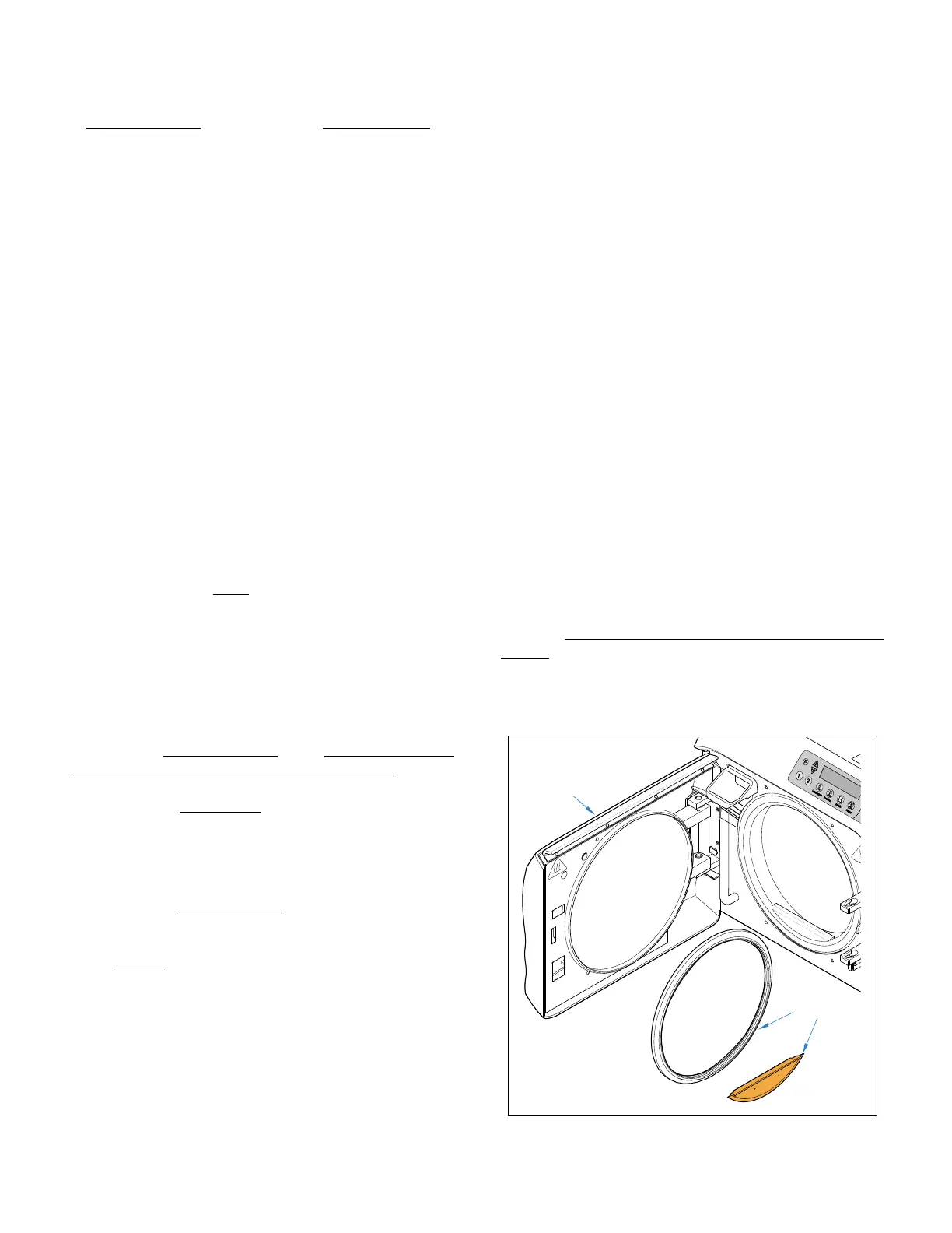
Door and Dam Gaskets (Fig. 1-2)
Seals door when in latched position to prevent pressure
from escaping around door during operation.
MA598904i
STEAM BLOCK
GASKET
DOOR & DAM
GASKETS
Figure 1-2.
Rev. 8/04/03
Return To Table of Contents