OM-278174 Page 12
F
Complete Parts List is available at www.MillerWelds.com
SECTION 4 – SPECIFICATIONS
4-1. Serial Number And Rating Label Location
The serial number and rating information for this product is located on the back of unit. Use rating label to determine input power requirements
and/or rated output. For future reference, write serial number in space provided on back cover of this manual.
4-2. Software Licensing Agreement
The End User License Agreement and any third-party notices and terms and conditions pertaining to third-party software can be found at
https://www.millerwelds.com/eula and are incorporated by reference herein.
4-3. Information About Default Weld Parameters And Settings
NOTICE – Each welding application is unique. Although certain Miller Electric products are designed to determine and default to certain typical
welding parameters and settings based upon specific and relatively limited application variables input by the end user, such default settings are
for reference purposes only; and final weld results can be affected by other variables and application-specific circumstances. The appropriate-
ness of all parameters and settings should be evaluated and modified by the end user as necessary based upon application-specific require-
ments. The end user is solely responsible for selection and coordination of appropriate equipment, adoption or adjustment of default weld
parameters and settings, and ultimate quality and durability of all resultant welds. Miller Electric expressly disclaims any and all implied warran-
ties including any implied warranty of fitness for a particular purpose.
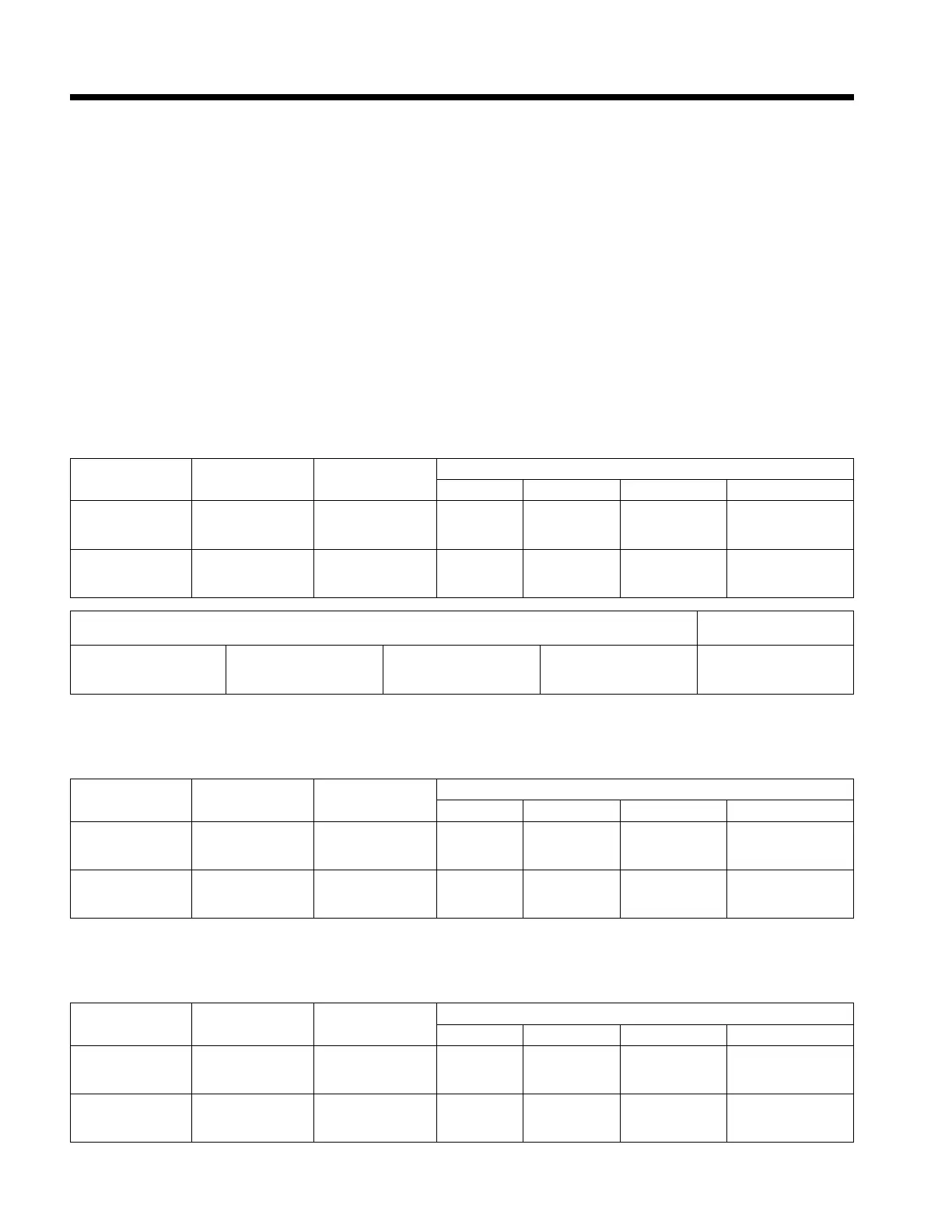
4-4. Unit Specifications For MIG (GMAW)
F
Do not use information in unit specifications table to determine electrical service requirements. See Sections 5-2 ,and 5-3 for information
on connecting input power.
Rated Welding
Output
Amperage Range
Maximum Open-
Circuit Voltage DC
Amperes Input at Rated Load Output, 50/60 Hz, Single-Phase
208 VAC 240 VAC 460 VAC 575 VAC
260 A at 27 Volts
DC, 40% Duty
Cycle
20–350 81 40.8 35 19.1 16.5
230 A at 25.5 Volts
DC, 60% Duty
Cycle
20–350 81 34.7 29.7 17.1 14.3
Wire Type And Diameter Wire Weed Speed
Range
Solid Steel .
.024 - .045 in.
(0.6 - 1.2 mm)
Flux Cored
.035 - .045 in.
(0.9 - 1.2 mm)
Aluminum
.035 - .047 in.
(0.9 - 1.3 mm)
Dual Shield
.045 in. (1.2 mm)
50 - 800 IPM
(1.2 - 17.8 m/min)
4-5. Unit Specifications For Stick (SMAW)
F
Do not use information in unit specifications table to determine electrical service requirements. See Sections 5-2, and 5-3 for information
on connecting input power.
Rated Welding
Output
Amperage Range
Maximum Open-
Circuit Voltage DC
Amperes Input at Rated Load Output, 50/60 Hz, Single-Phase
208 VAC 240 VAC 460 VAC 575 VAC
240 A at 29.6 Volts
DC, 40% Duty
Cycle
30–275 81 42 36.1 20.1 16.8
200 A at 28 Volts
DC, 60% Duty
Cycle
30–275 81 33.5 29 16.4 13.6
4-6. Unit Specifications For TIG (GTAW)
F
Do not use information in unit specifications table to determine electrical service requirements. See Sections 5-2, and 5-3 for information
on connecting input power.
Rated Welding
Output
Amperage Range
Maximum Open-
Circuit Voltage DC
Amperes Input at Rated Load Output, 50/60 Hz, Single-Phase
208 VAC 240 VAC 460 VAC 575 VAC
275 A at 21 Volts
DC, 60% Duty
Cycle
5–275 81 34.1 29.9 17 14.1
230 A at 19.2 Volts
DC, 100% Duty
Cycle
5–275 81 26.7 23.2 13.5 11.1