OM-278174 Page 23
F
Complete Parts List is available at www.MillerWelds.com
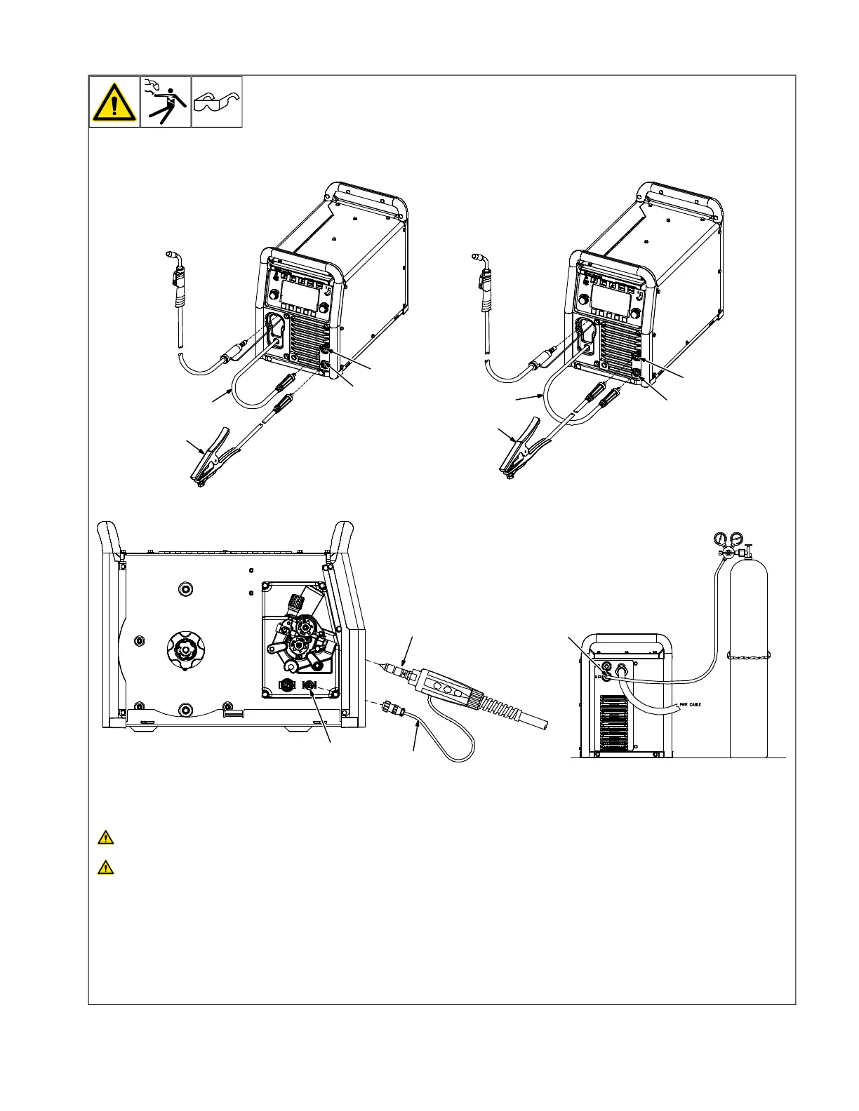
5-9. MIG Welding Connections
MIG/FCAW-G − DCEP
(Direct Current Electrode Positive)
FCAW-S − DCEN
(Direct Current Electrode Negative)
1
4
3
2
4
3
2
8
1
6
7
5
Turn off unit and disconnect input
power before making connections.
Do not use worn, damaged, under-
sized, or repaired cables.
1 Positive Weld Output Receptacle
2 Negative Weld Output Receptacle
3 Wire Drive Assembly Cable
4 Work Clamp And Cable
Ensure all connections are tight.
5 Gun End
Connect gun end to drive assembly (see
Section 5-10).
6 Trigger Control Cable
7 Four Pin Trigger Control Cable
Receptacle
Route trigger control cable through MIG gun
hole.
Connect plug on end of cable to four pin re-
ceptacle inside unit.
8 MIG Shielding Gas Connection
Connect supplied gas hose between regula-
tor/flowmeter gas hose connection and fit-
ting on rear panel of power source (see
Section 5-13).