OM-278174 Page 64
SECTION 10 – GMAW WELDING (MIG) GUIDELINES
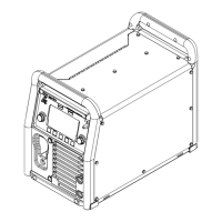
10-1. Typical GMAW (MIG) Process Connections
OM-
1
2
3
4
5
6
7
1/16 in.
(0.0625 in.)
2
1
3
4
Weld current can damage electronic
parts in vehicles. Disconnect both
battery cables before welding on a
vehicle. Place work clamp as close
to the weld as possible.
1 Wire Feeder/Welding Power Source
2 Gun
3 Workpiece
4 Work Clamp
5 Gas
6 Shielding Gas
7 Regulator/Flowmeter
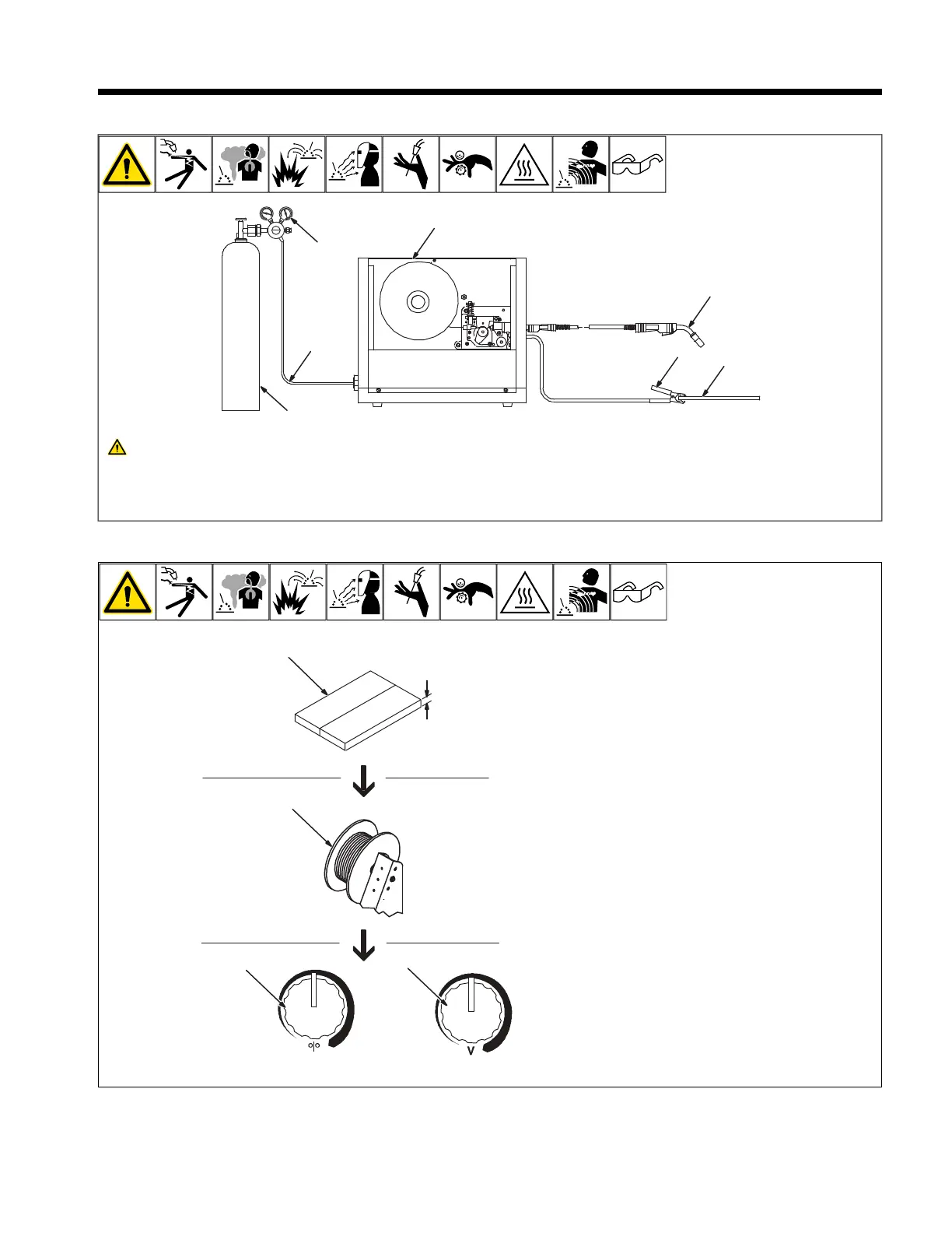
10-2. Typical GMAW (MIG) Process Control Settings
OM-
1
2
3
4
5
6
7
1/16 in.
(0.0625 in.)
2
1
3
4
F
These settings are guidelines only. Ma-
terial and wire type, joint design, fitup,
position, shielding gas, etc. affect set-
tings. Test welds to be sure they comply
to specifications.
1 Material Thickness
Material thickness determines weld
parameters.
Convert material thickness to amperage (A):
0.001 in. (0.025 mm) = 1 ampere
0.0625 in. (1.59 mm) ÷ 0.001 = 62.5 A
2 Select Wire Size
See table below.
3 Select Wire Feed Speed (Amperage)
Wire feed speed (amperage) controls weld
penetration. See table below.
4 Select Voltage
Voltage controls height and width of weld
bead.
Low Voltage: wire stubs into work
High Voltage: arc is unstable (spatter)
Set voltage midway between high and low
voltage.