OM-278174 Page 19
F
Complete Parts List is available at www.MillerWelds.com
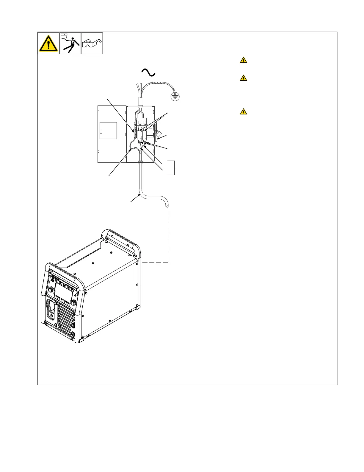
5-3. Connecting 1-Phase Input Power
2
1
L1
L2
1
=GND/PE Earth Ground
6
5
3
4
7
Installation must meet all National
and Local Codes—have only quali-
fied persons make this installation.
Disconnect and lockout/tagout in-
put power before connecting input
conductors from unit. Follow es-
tablished procedures regarding
the installation and removal of
lockout/tagout devices.
Always connect green or green/
yellow conductor to supply
grounding terminal first, and never
to a line terminal.
See rating label on unit and check input volt-
age available at site.
1 Input Power Cord
2 Disconnect Device (switch shown in the
OFF position)
3 Disconnect Device Grounding Terminal
4 Disconnect Device Line Terminals
5 Black And White Input Conductor (L1
And L2)
6 Green Or Green/Yellow Grounding
Conductor
Connect green or green/yellow grounding
conductor to disconnect device grounding
terminal first.
Connect input conductors L1 and L2 to dis-
connect device line terminals.
7 Over-Current Protection
Select type and size of over-current protec-
tion using Electrical Service Guide (fused
disconnect switch shown).
Close and secure door on disconnect device.
Follow established lockout/tagout proce-
dures to put unit in service.