OM-225 389 Page 12
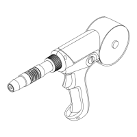
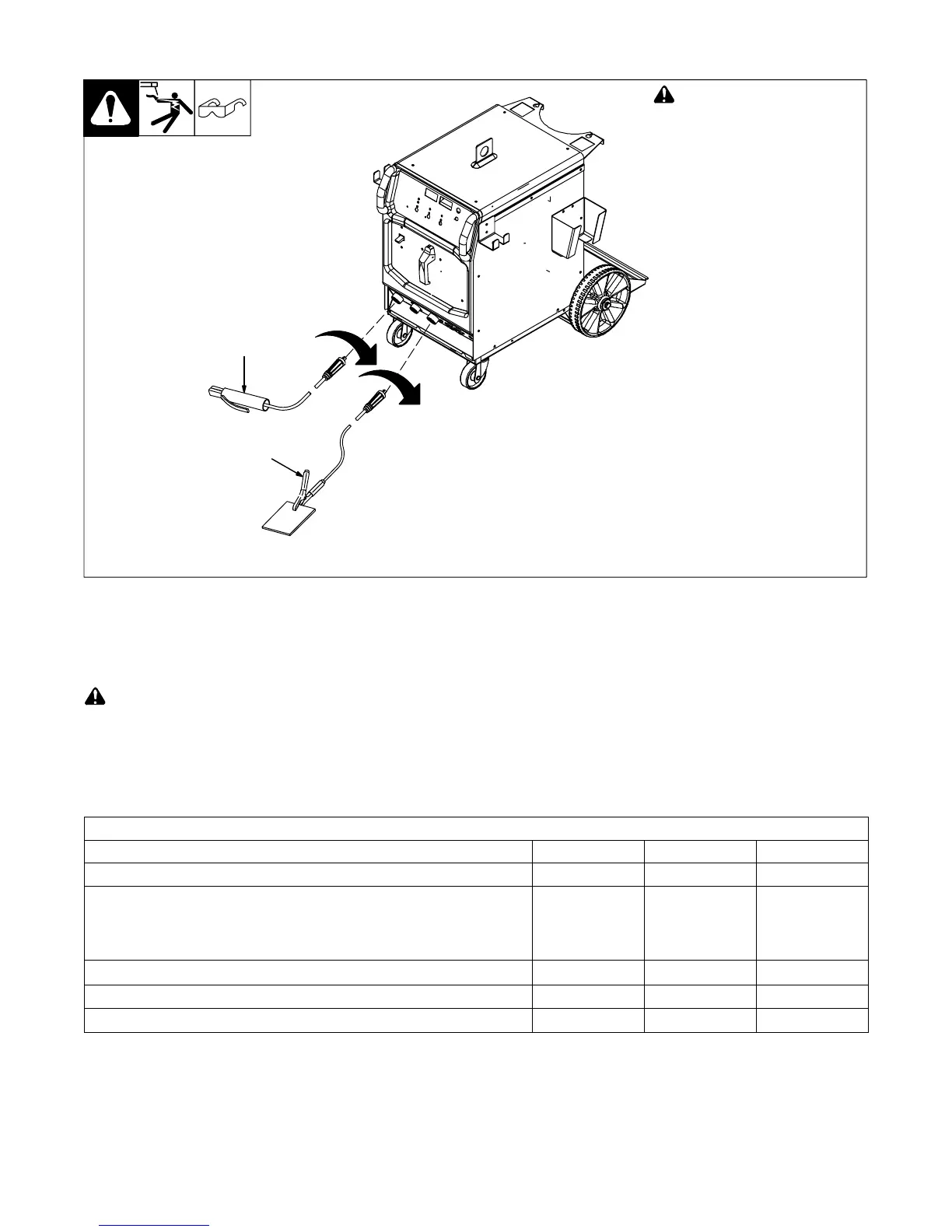
2-14. Typical Stick Connections
! Turn off power before mak-
ing connections.
1 Electrode Holder
2 Work Clamp
Connect electrode holder and work
clamp to receptacles as shown.
1
2
2-15. Electrical Service Guide
Failure to follow these electrical service guide recommendations could create an electric shock or fire hazard. These recommenda-
tions are for a dedicated branch circuit sized for the rated output and duty cycle of the welding power source.
. All values calculated at 40% duty cycle.
. Actual input voltage cannot exceed ± 10% of indicated required input voltage shown in table. If actual input voltage is outside of this range, damage
to unit may occur.
50/60 Hz Single Phase
Input Voltage 208-230 460 575
Input Amperes At Rated Output 54 27 22
Max Recommended Standard Fuse or circuit breaker Rating In Amperes
1
Time-Delay
2
60 30 25
Normal Operating
3
80 40 30
Min Input Conductor Size In AWG
4
8 12 14
Max Recommended Input Conductor Length In Feet (Meters) 147 (45) 249 (76) 256 (78)
Min Grounding Conductor Size In AWG
4
8 12 14
Reference: 2008 National Electrical Code (NEC) (including article 630)
1 If a circuit breaker is used in place of a fuse, choose a circuit breaker with time-current curves comparable to the recommended fuse.
2 “Time-Delay” fuses are UL class “RK5”. See UL 248.
3 “Normal Operating” (general purpose - no intentional delay) fuses are UL class “K5” (up to and including 60 amps), and UL class “H” ( 65 amps and
above).
4 Conductor data in this section specifies conductor size (excluding flexible cord or cable) between the panelboard and the equipment per NEC Table
310.16. If a flexible cord or cable is used, minimum conductor size may increase. See NEC Table 400.5(A) for flexible cord and cable requirements.
Reference: 2005 National Electrical Code (NEC)