OM-225 389 Page 40
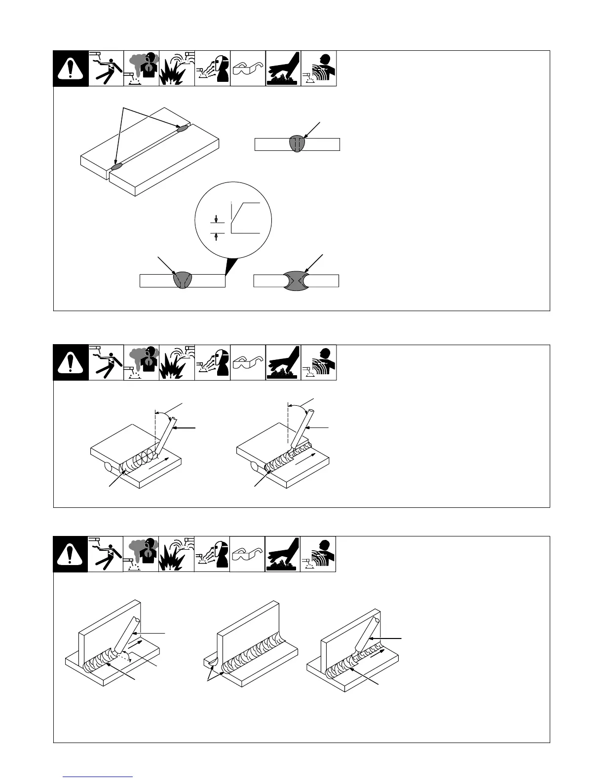
9-9. Butt Joints
S-0062
1 Tack Welds
Prevent edges of joint from draw-
ing together ahead of electrode by
tack welding the materials in posi-
tion before final weld.
2 Square Groove Weld
Good for materials up to 3/16 in. (5
mm) thick.
3 Single V-Groove Weld
Good for materials 3/16 − 3/4 in.
(5-19 mm) thick. Cut bevel with
oxyacetylene or plasma cutting
equipment. Remove scale from
material after cutting. A grinder can
also be used to prepare bevels.
Create 30 degree angle of bevel on
materials in V-groove welding.
4 Double V-Groove Weld
Good for materials thicker than
3/16 in. (5 mm).
30°
2
1
1/16 in.
(1.6 mm)
3
4
9-10. Lap Joint
S-0063 / S-0064
1 Electrode
2 Single-Layer Fillet Weld
Move electrode in circular motion.
3 Multi-Layer Fillet Weld
Weld a second layer when a heavi-
er fillet is needed. Remove slag be-
fore making another weld pass.
Weld both sides of joint for maxi-
mum strength.
30°
Or Less
30°
Or Less
1
1
2
3
9-11. Tee Joint
S-0060 / S-0058-A / S-0061
1 Electrode
2 Fillet Weld
Keep arc short and move at defi-
nite rate of speed. Hold electrode
as shown to provide fusion into the
corner. Square edge of the weld
surface.
For maximum strength weld both
sides of upright section.
3 Multi-Layer Deposits
Weld a second layer when a heavi-
er fillet is needed. Use any of the
weaving patterns shown in Section
9-8. Remove slag before making
another weld pass.
45°
Or
Less
1
2
1
3
2